AC Amplitude (high-impedance) Adjustment (Channel 2)
AC Amplitude (high-impedance) Adjustment (Channel 2)
The instrument stores a calibration constant for each high-impedance attenuator path. Each path's gain coefficient is
calculated using two measurements: one with the waveform DAC at + output and one with waveform DAC at – out-
put. The setups, therefore, must be performed in pairs.
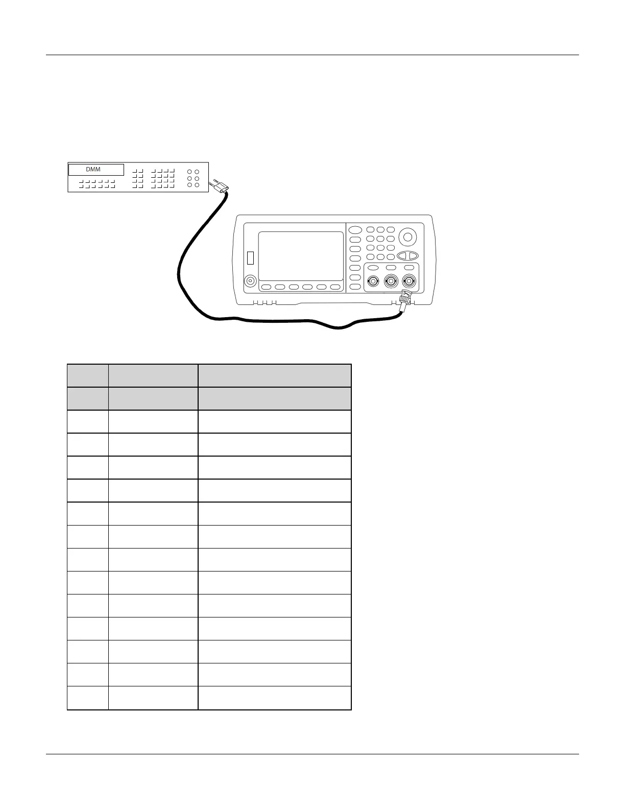
1. Connect the DMM to the channel output as shown below.
2. Use the DMM to measure the DC voltage at the front-panel connector for each setup in the following table.
Nominal Signal
Setup DC Level
57 +0.0028 V Output of -72 dB range
58* - 0.0028 V Output of -72 dB range
59 +0.007 V Output of -64 dB range
60* -0.007 V Output of -64 dB range
61 +0.017 V Output of -56 dB range
62* -0.017 V Output of -56 dB range
63 +0.044 V Output of -48 dB range
64* -0.044 V Output of -48 dB range
65 +0.11 V Output of -40 dB range
66* -0.11 V Output of -40 dB range
67 +0.28 V Output of -32 dB range
68* -0.28 V Output of -32 dB range
69 +0.68 V Output of -24 dB range
Agilent 33500 Series Operating and Service Guide 401

 Loading...


