EasyManuals Logo

Agilent Technologies Agilent 3499A User Manual

Agilent Technologies Agilent 3499A
357 pages
To Next Page IconTo Next Page
To Previous Page IconTo Previous Page
Page #211 background imageLoading...
Page #211 background image
211
Chapter 7 Plug-in Modules
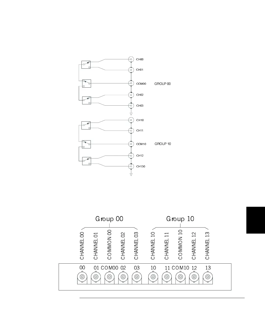
N2268A 50 3.5 GHz Dual 1-to-4 MUX Module
4
7
One channel in each group is connected to the common terminals. By
default, COM00 is connected to CH00 and COM10 is connected to CH10.
N2268A Wiring Information
The rear panel of the N2268A is shown below. Use male SMA connectors
to connect external signals to the N2268A module.
CH00
CH01
COM00
CH03
CH02
CH10
CH11
COM10
CH12
CH130
GROUP 00
GROUP 10
CH ANNE L 00
CH ANNE L 03
CH ANNE L 02
COMMON 00
CH ANNE L 01
CH ANNE L 10
CH ANNE L 13
CH ANNE L 12
COMMON 10
CH ANNE L 11
Group 00 Group 10
00
01 COM00 02 03 10
11
COM10
12
13

Table of Contents

Questions and Answers:

Question and Answer IconNeed help?

Do you have a question about the Agilent Technologies Agilent 3499A and is the answer not in the manual?

Agilent Technologies Agilent 3499A Specifications

General IconGeneral
BrandAgilent Technologies
ModelAgilent 3499A
CategoryControl Systems
LanguageEnglish