272
Chapter 7 Plug-in Modules
Protection Networks
7
Protection Networks
This information applies specifically to the N2267A (page 206) and
44471A (page 236) multiplexer modules. These multiplexers have
provisions built in to allow you to add custom protection networks. This
information is general and may be used to help you design other relay
protection circuits.
Protection networks are especially needed if the loads being switched are
inductive loads such as incandescent lamps or electric motors. The
resistance of these loads is very low when the power is first applied (for
example, the transient inrush current when switching on a lamp could
be 15 times the steady-state value). When switching off inductive loads,
the counter EMF of the coil can generate high voltage across the relay
contacts, and may damage the contacts.
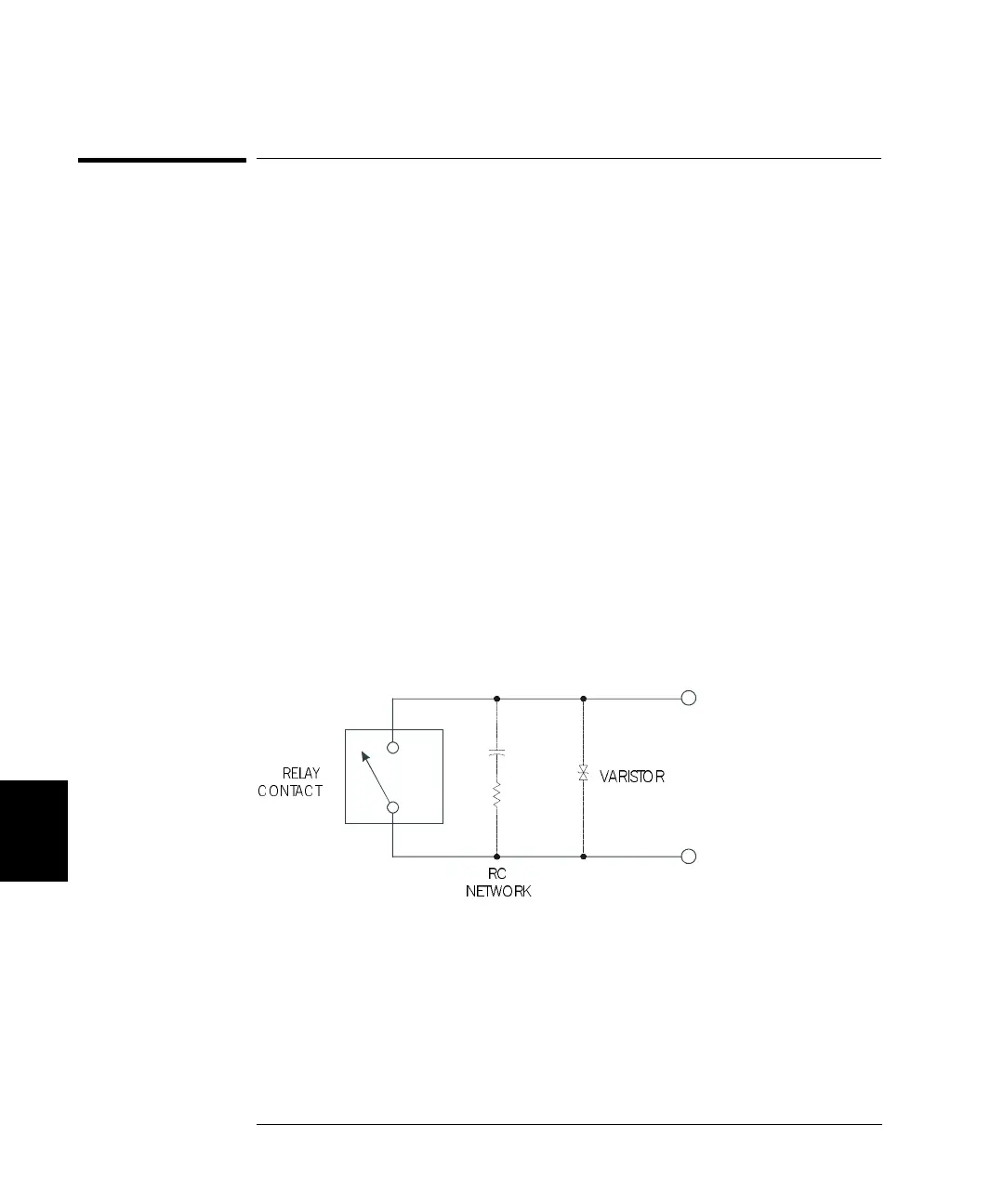
Current limitation circuitry should be used to prevent relay contacts
from being damaged. Space to mount a protection network is designed on
the PC board to avoid this damage. Either an RC network or a varistor
can effectively absorb the high voltage surge. The specifications of
protection components are determined by the loads that are connected to
the multiplexer. A typical protection circuit for relay contacts is
illustrated below.
RELAY
CONTAC T
RC
NETWORK
VARISTO R
 Loading...