342
Chapter 9 Specifications
44475A Breadboard Module
9
44475A Breadboard Module
Components required, but not supplied, are to be mounted on the
Breadboard. Refer to the manufacturers data sheet for load/drive
specifications of these components see page 251 for a list of required
components).
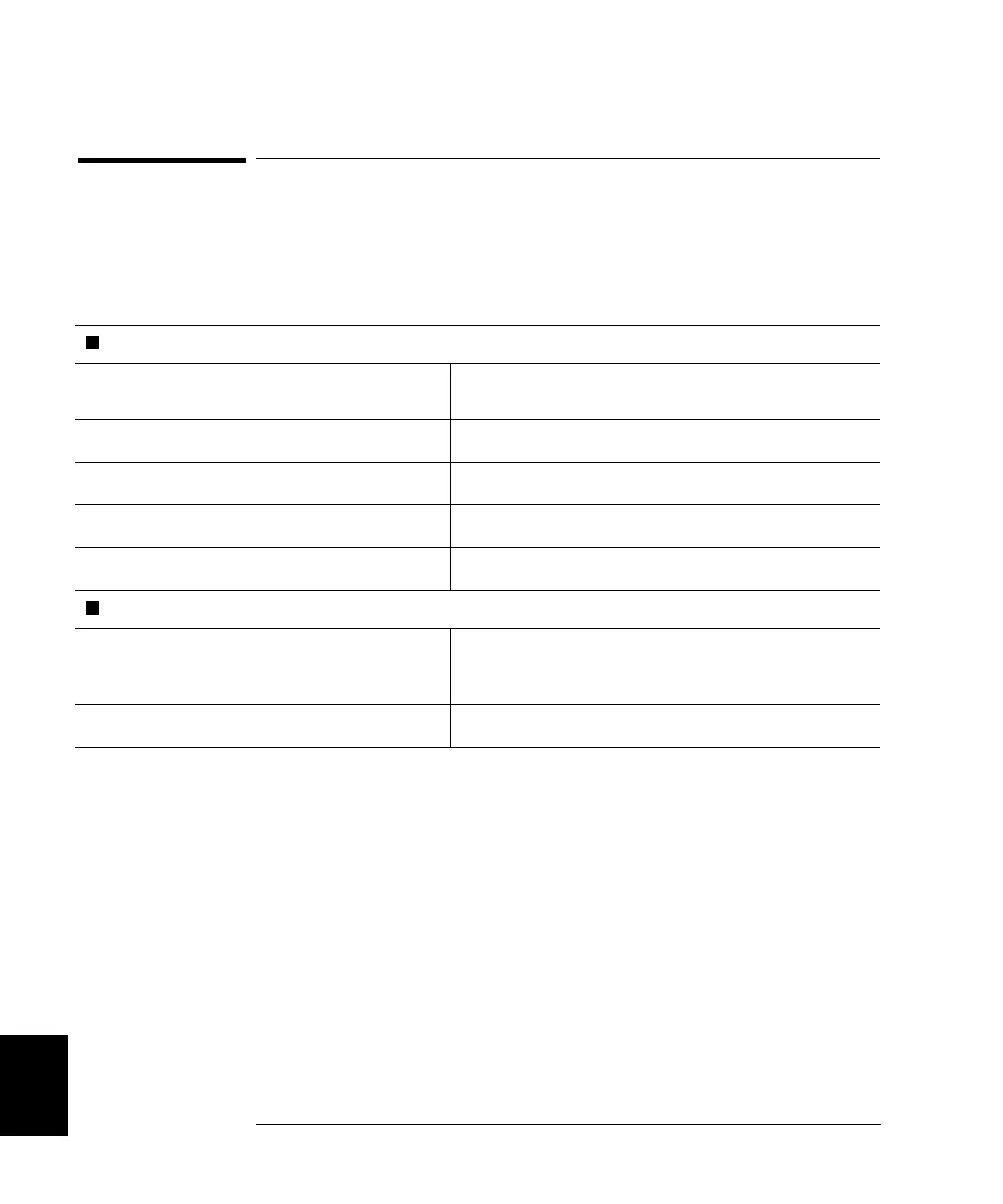
MODULE DIMENSIONS
Component Area Available:
104mm x 74mm and 79mm x 74mm
(4.1” x 2.9” and 3.1” x 2.9”)
Grid Hole Spacing (center-center):
2.54mm x 2.54 mm (0.1” x 0.1”)
Grid Hole Size (inside diameter):
1.17mm (0.046”)
Maximum Component Height (above board):
12.7mm (0.5”)
Maximum lead Length (below board):
3.2mm (0.125”)
INPUT CHARACTERISTICS
Maximum Voltage:
42 V dc, 30 V ac rms, 42 V ac peak
(on breadboard area);
5.5 V (on digital input port lines)
Maximum Power Dissipation (Per Module):
2 Watts
 Loading...