255
Chapter 7 Plug-in Modules
44475A Breadboard Module
4
7
2 Install your custom circuitry.
Component height restrictions and how far the component leads extend
through the circuit board are limited by the top and bottom shields.
These shields provide RF shielding as well as structural strength and
must never be eliminated.
The maximum component height allowed is 12.7 mm (0.50 in.). However,
if the height of any component exceeds 10 mm, the conductive surface of
the component must be insulated. On the circuit side of the Breadboard,
the lead lengths are limited to 3.2 mm (0.125 in.) from the circuit board.
3 Assemble the hardware.
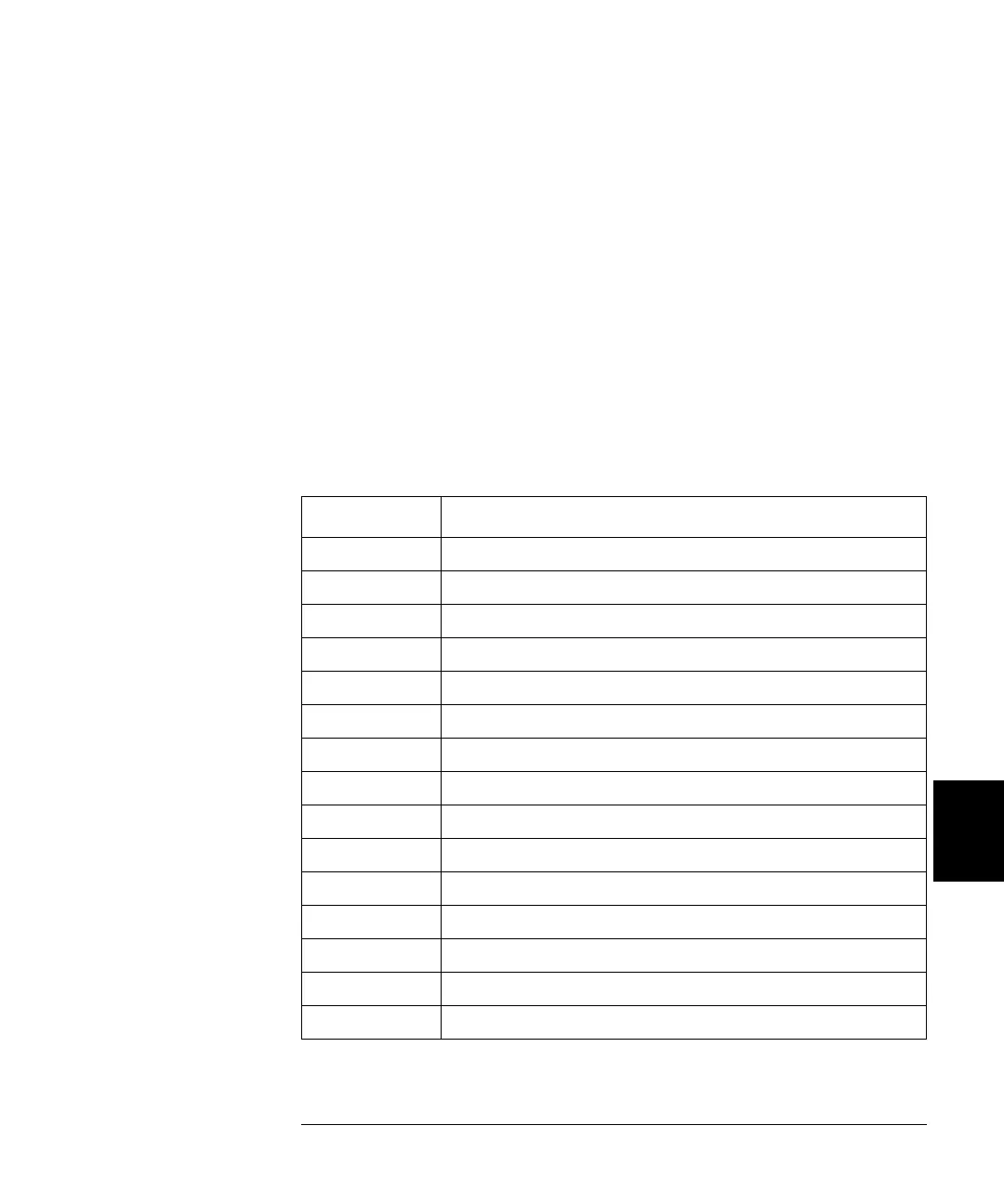
The table below lists the hardware parts that are supplied with the
44475A. An assembly diagram is given on the next page.
Part Number Description
44475-26501 Breadboard circuit board
03488-00602 Bottom shield
03488-00603 Top shield (component side)
1251-8645 2 rows x 15 pins right angle connector (small connector)
44475-62102 2 rows x 11 pins right angle connector (large connector)
44475-62101 Terminal Block, keyed for the breadboard connector
5040-5193 Connector Housing
0515-5194 Cable Clamp
0515-0063 Pan Head screw, 2.5 x 12 (metric)
0515-0843 Flat Head screw, 2.5 x 20 Lock (metric)
0515-0045 Pan Head screw, 3 x 18 Lock (metric)
0535-0004 Hex Nut, 3 x 0.5
0535-0008 Hex Nut, 2.5 x 0.45
2190-0583 Lock Washer
2190-0584 Lock Washer
 Loading...