258
Chapter 7 Plug-in Modules
44476A Microwave Switch Module
7
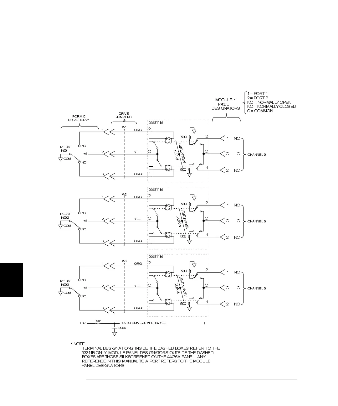
44476A Simplified Schematic
A simplified schematic is given below. The 44476A contains three 8762B
Microwave Switches. Each microwave switch is referred to as a channel.
The channels on the 44476A are numbered as 00, 01, and 02.
DRIVE
JUMPERS
FORM C
DRIVE RELA Y S
+5V
L901
C906
+5 TO DRIVE JUMPERS (YEL )
RELAY
K901
COM
NO
NC
+5
1
2
3
ORG
YEL
ORG
W1
CHANNEL 0
50
Ω
50
Ω
33311B
2
C
1
2
C
1
1
C
2
NO
C
NC
RELAY
K903
COM
NO
NC
+5
1
2
3
ORG
YEL
ORG
W3
CHANNEL 0
50
Ω
50
Ω
33311B
2
C
1
2
C
1
1
C
2
NO
C
NC
RELAY
K902
COM
NO
NC
+5
1
2
3
ORG
YEL
ORG
W2
CHANNEL 0
50
Ω
50
Ω
33311B
2
C
1
2
C
1
1
C
2
NO
C
NC
MODUL E *
PANEL
DESIG NATORS
1=PORT1
2=PORT2
NO = NORMA LLY OPE N
NC = NORMA LLY CLOSE
C = COMMO N
* NOTE :
TERMINAL DESIGNATIONS INS ID E THEDASHED BOXES REFER TO THE
333 11B ONLY . MODULE PANE L DESIGNATORS OUTSIDE THE DASHE D
BOXES ARE THOSE SILKSCREENED ON THE 444 76A PANEL. ANY
REFERENCE IN THIS MANUAL TO A PORT REFERS TO THE MODULE
P
I
V
O
T
A
R
M
A
T
U
R
E
P
I
V
O
T
A
R
M
A
T
U
R
E
P
I
V
O
T
A
R
M
A
T
U
R
E
 Loading...