269
Chapter 7 Plug-in Modules
44478A/B 1.3 GHz Dual 4-to-1 MUX Modules
4
7
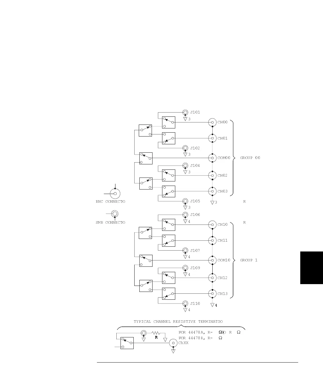
44478A Simplified Schematic
A simplified schematic is shown below. The two groups of 4-to-1 MUXs
are specified as GROUP 00 and GROUP 10. They are isolated from each
other. Closing a channel closes a particular set of relays to connect the
common BNC to one of the four BNC inputs. Channels within each group
are break-before-make and are numbered as 00 through 03 for GROUP
00 and 10 through 13 for GROUP 10.
3
CH00
CH01
J101
3
J102
3
CH02
CH03
J104
3
J105
COM00
3
GROUP 00
4
CH11
CH10
J106
4
J107
4
CH12
CH13
J109
4
J110
COM10
GROUP 1
BNC CONNECTO R
SMB CONNECTO R
TYPICAL CHANNEL RESISTIVE TERMINATIO
ChXX
FOR 44478B, R=
Ω
FOR 44478A, R= 50O R
Ω( Ω
 Loading...