287
Chapter 7 Plug-in Modules
Terminals and Connections Information
4
7
4448x Screw Terminal Blocks
Screw terminal blocks are available for the 44470D and 44471D plug-in
modules. One of these terminals is shipped with each plug-in module.
Refer to the specific plug-in module wiring information for details about
the terminal block. The figures below shows the basic steps to wire and
assemble this type of terminal.
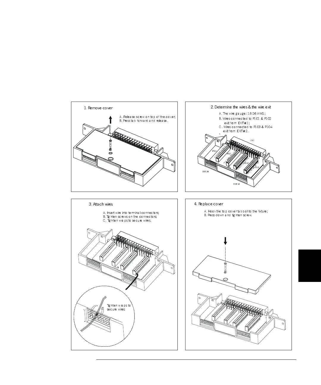
1. Remove cover
2. Det e r mine the wir es & the wir e exit
P10 1
P10 2
P10 3
P 104
J101
EXIT 1#
EXIT 2 #
B. Wires connected to P101 & P102
exit from EXIT#1;
C. Wires connected to P103 & P104
e xit fro m EXIT# 2.
3. Attach wires
A. Inse rt wire into te rm in a l c o nn e c to rs;
B. Tighten screws on the connectors;
C . T ig h te n wra p s to se c ure wire s.
Tighten wraps to
se c ure w ire s
4. Replace c over
A. Hookthe top covertabs onto the fixture;
B. Press down and tighten screw.
A. Re le a se sc rew o n to p o f the c o v e r ;
B. Press tab forward and release.
A. The wire g a u ge: 18-26 AWG;
 Loading...