73
Chapter 3 System Overview
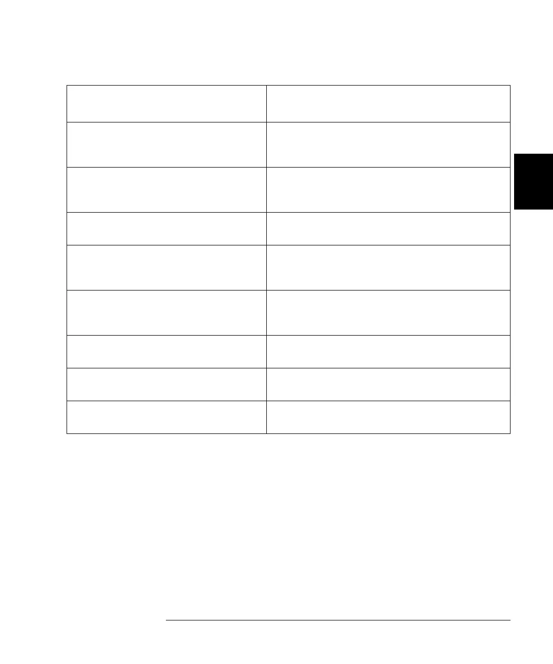
Channel and Slot Addressing
4
3
44473A
4x4 Matrix Module
Row: 0, 1, 2, 3; Column: 0, 1, 2, 3
(
s00, s01, s02, s03; s10, s11, s12, s13;
s20, s21, s22, s23; s30, s31, s32, s33)
a
44474A
16-Bit Digital I/O Module
Individual Bits: s00, s01, s02... s14, s15
8-Bit Ports: s00, s01
16-Bit Port: s00
44475A
Breadboard Module
N/A
44476A
3-Channel 13 GHz Microwave
Switch Module
s00, s01, s02
44476B
2-Channel 26 GHz Microwave
Switch Module
s00, s01
44477A
7-Channel Form-C Relay Module
s00, s01, s02, s03, s04, s05, s06
44478A
50
Ω
1.3 GHz MUX Module
Group 0: s00, s01, s02, s03
Group 1: s10, s11, s12, s13
44478B
75
Ω
1.3 GHz MUX Module
Group 0: s00, s01, s02, s03
Group 1: s10, s11, s12, s13
a. A channel number on a matrix module is formed in Slot-Row-Column format, i.e., channel address s23 means row 2,
column 3 in Slot s.
Plug-in Module
Channel Addressing (snn)
s = Slot Number; nn = Channel Number
 Loading...