81
Chapter 4 Features and Functions
Monitoring a Channel or a Slot
4
4
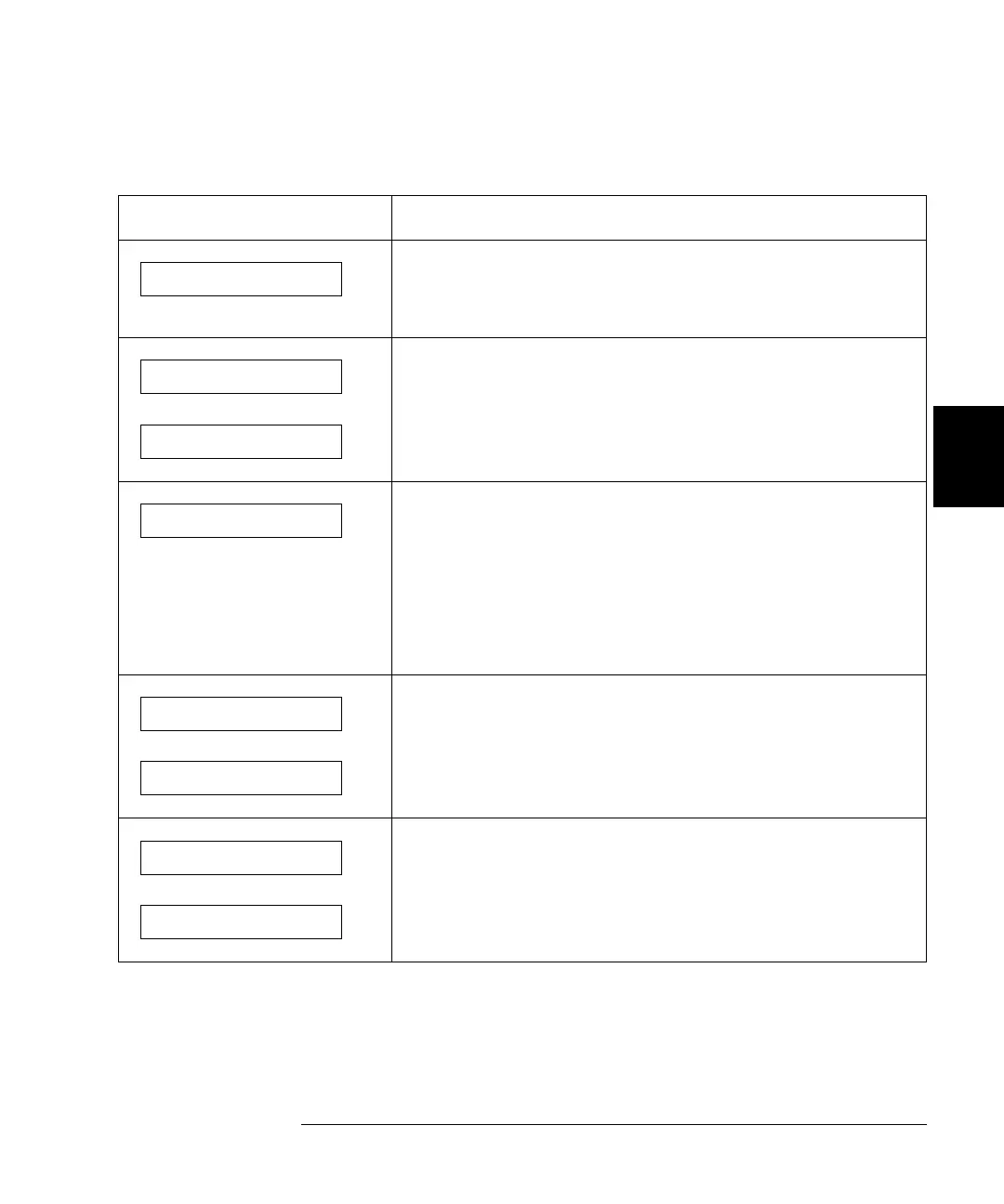
Example MON Display Description
The display for a multiplexer or a GP relay module. This
display indicates that the monitored module is in Slot 2 and
channels 10, 16, and 19 are closed.
The display for a matrix module. The top display is the row
information, indicating that the relays on Row 3, Columns 1, 3,
6 and 7 of the module (in Slot 3) are closed. The lower display
is the column information, indicating that relays on column 3,
row 0 and 3 are closed.
The display for a digital I/O module. The first 2 digits on the left
(“00” in this case) represents the “L” 8-bit port address. Adding
one to this value, the “H” 8-bit port address is obtained. Data
with a trailing decimal point indicates that the last operation on
that port was a WRITE, data without a trailing decimal point
indicates that the last operation on that port was a READ. This
display shows that the data last read from Port 401 is 255 and
the data last written to Port 400 was 254.
The top display is for the built-in digital I/O Port 090 (controller
module) and the data from the last operation. The lower
display indicates that data last written to the bit channel
091 is 0.
For a multifunction module, the first function on the module is
displayed, then the next. This display is an example of a
multifunction module with matrix and DIO functions (in slot 5).
1:0,,,,,,6,,,9, 2
ROW 3:,1,,3,,,6,7 3
0;,,3,COL 3, 3
00:H255 L254. 4
DIO 12 090
DOUT 0 091
ROW 0:,1,,3, 5
00:H255 L254. 5
 Loading...