Home
Agilent Technologies
Measuring Instruments
E4418B
Agilent Technologies E4418B User Manual
5
of 1
of 1 rating
199 pages
Give review
Manual
Specs
To Next Page
To Next Page
To Previous Page
To Previous Page
Loading...
2
Power Meter Operation
54
E4418B Power Meter User’s Guide
Selecting a Frequency Dependent Offset T
able
Y
ou can select a frequency dependent
offset t
able for use b
y pressing
,
,
,
. The
“St
ate” f
ield
indicates if any frequency dependent of
fset t
ables are cur
rently selected.
The “Offset Tbls” screen
is displa
yed as sho
wn in
Fig
ure
2-
6
.
Figure 2-6
“Offset Tbls” Screen
Tables
Fre
q De
p Off
set
Table Off On
77
79
Table of Contents
Default Chapter
3
Warranty
3
Limitation of Warranty
3
Exclusive Remedies
4
Warnings and Cautions
4
Safety Symbols
5
Personal Safety Considerations
6
General Safety Considerations
6
Regulatory Markings
7
IEC 1010-1 Compliance
8
Statement of Compliance
8
Installation Instructions
8
Regulatory Information
9
List of Related Publications
11
Agilent Technologies E4418B Options
12
About this Guide
13
Table of Contents
15
List of Tables
23
1 Getting Started
26
Introduction
26
Turning on the Power Meter
27
The Front Panel at a Glance
29
The Display Layout
32
Table 1-1 Relevant Softkeys in Various Mode of Operation
34
Table 1-2 List of Possible Combinations for the Upper and Lower Display Lines
34
Selecting Your Display Layout
35
Window Symbols
38
Warning Symbol
38
Confirmation Window
38
Wait Symbol
39
One of N Entry Window
39
Numeric or Alphanumeric Entry Window
39
The Rear Panel at a Glance
40
Adjusting the Carrying Handle
42
Rack Mounting the Power Meter
43
2 Power Meter Operation
45
Introduction
46
Battery Operation (Option 001)
48
General Information
48
Running Time
49
Figure 2-1 Battery Status
49
Charging Times
50
Backlight
50
Battery Removal/Replacement
51
Figure 2-2 Battery Removal/Replacement
52
Zeroing and Calibrating the Power Meter
53
Zeroing the Power Meter
53
Zero/Cal Lockout
53
Calibrating the Power Meter
54
Calibration Procedure Using Agilent E-Series Power Sensors and N8480 Series Power Sensors (Excluding Option CFT)
54
Calibration Procedure Using Agilent 8480 Series Power Sensors and N8480 Series Power Sensors with Option CFT
55
Table 2-1 Power Sensor Connection Requirements
57
Zeroing and Calibrating Using TTL Inputs
59
Figure 2-3 Rmt I/O Port TTL Inputs
59
Table 2-2 TTL Inputs Control Logic
59
Table 2-3 TTL Input Timing Diagram 1
60
Table 2-4 TTL Inputs Timing Diagram 2
61
Making Measurements with the Agilent E-Series Power Sensors and N8480 Series Power Sensors (Excluding Option CFT)
63
Procedure
63
Making Measurements with the Agilent 8480 Series Power Sensors and N8480 Series Power Sensors with Option CFT
65
Procedure
65
Making Measurements Using Sensor Calibration Tables
68
Selecting a Sensor Calibration Table
69
Making the Measurement
69
Figure 2-4 "Sensor Tbls" Screen
69
Editing Sensor Calibration Tables
70
Figure 2-5 "Edit Cal Screen
71
Making Measurements Using Frequency Dependent Offset Tables
77
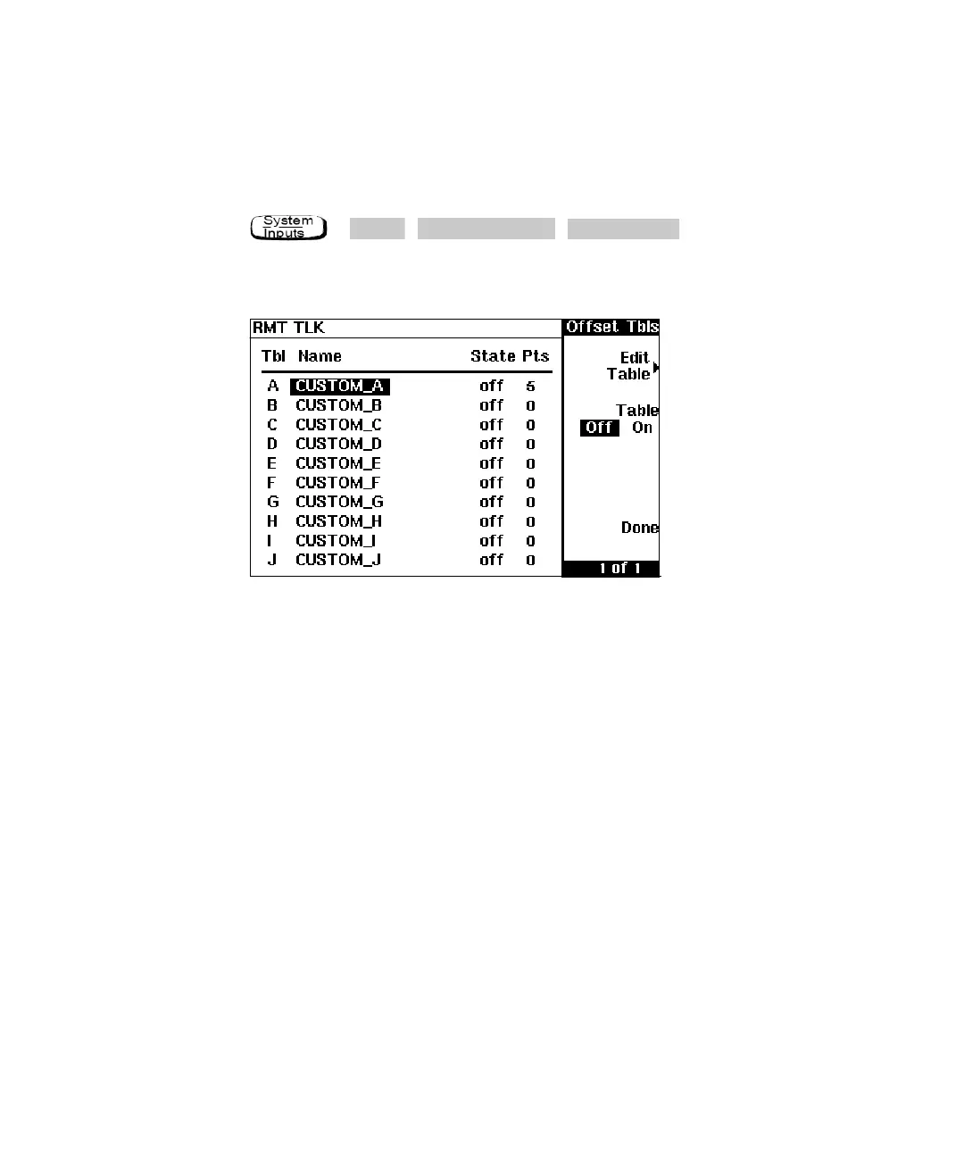
Selecting a Frequency Dependent Offset Table
78
Figure 2-6 "Offset Tbls" Screen
78
Making the Measurement
79
Editing Frequency Dependent Offset Tables
80
Figure 2-7 "Edit" Screen
80
Setting the Units of Measurement
83
Table 2-5 Measurement Units
83
Selecting Units of Measurement from the Softkeys
84
Making Relative Measurements
85
Procedure
85
Setting the Resolution
86
Setting Offsets
87
Setting Channel Offsets
87
Setting Display Offsets
88
Figure 2-8 Effect of Offsets on a Channel Measurement
88
Setting Averaging
89
Figure 2-9 Averaged Readings
90
Step Detection
91
Measuring Pulsed Signals
92
Figure 2-10 Pulsed Signal
92
Setting Measurement Limits
94
Setting Channel Limits
94
Figure 2-11 Limits Checking Application
95
Figure 2-12 Limits Checking Results
95
Setting Window Limits
96
Table 2-6 Range of Values for Window Limits
96
Figure 2-13 Remote I/O TTL Outputs
97
Checking for Limit Failures
98
Figure 2-14 Pass/Fail Limit Indicators
99
Selecting a Digital or Analog Display
100
Figure 2-15 Digital Display
100
Figure 2-16 Analog Display
100
Figure 2-17 Digital and Analog Display
100
Setting the Range
103
Configuring the Remote Interface
104
Gpib
104
Rs232/Rs422
105
Figure 2-18 RS232/ 422 Pin Assignment
105
Remote Interface Overview
107
Figure 2-19 Interface Overview Examples
108
Programming Language Selection
109
Recorder Output
110
Figure 2-20 Test Setup for Recording Swept Measurements
110
Leveling a Source Output
111
Saving and Recalling Power Meter Configurations
112
Figure 2-21 "Save/Recall" Screen
113
How Measurements Are Calculated
114
Figure 2-22 How Measurements Are Calculated
114
Presetting the Power Meter
115
Preset Conditions
115
Self Test
118
Power on Self Test
118
Front Panel Selection of Self Tests
119
Remote Testing
121
Test Descriptions
122
Operator Maintenance
125
Replacing the Power Line Fuse
125
Figure 2-23 Replacing the Fuse
126
Contacting Agilent Technologies
127
Before Calling Agilent Technologies
127
Check the Basics
128
Instrument Serial Numbers
128
Sales and Service Offices
130
Returning Your Power Meter for Service
131
3 Menu Reference
134
Introduction
134
The Front Panel Menu Maps
135
Dbm/W Menu
135
Frequency/Cal Fac Menu
136
Meas Setup Menu
137
Rel/Offset Menu
138
Save/Recall Menu
138
System Inputs Menu (1 of 4)
139
System Inputs Menu (2 of 4)
140
System Inputs Menu (3 of 4)
141
System Inputs Menu (4 of 4)
142
Zero/Cal Menu
143
Front Panel Menu Reference
144
Table 3-1 Combination of Sensor Type and Correction Applied to Current Measurement
145
Diagrammatical Keys
166
4 Error Messages
169
Introduction Error Messages
169
Introduction
170
Figure 4-1 Error Annunciator Position
170
Error Messages
172
5 Specifications
180
Introduction
180
Power Meter Specifications
181
Meter
181
Accuracy
182
Table 5-1 Zero Set Specifications
182
Mw Power Reference1
184
Power Meter Supplemental Characteristics
185
Measurement Speed
185
Zero Drift of Sensors
185
Measurement Noise
186
Table 5-2 Noise Multiplier
186
Table 5-3 Power Sensor Specifications
186
Settling Time
189
Table 5-4 Settling Time
189
Table 5-5 Settling Time
190
Table 5-6 Settling Time
192
Power Sensor Specifications
193
Battery Option 001 Operational Characteristics
194
General Characteristics
195
Rear Panel Connectors
195
Environmental Characteristics
196
General Conditions
196
Operating Environment
196
Storage Conditions
196
General
197
Dimensions
197
Weight
197
Safety
197
Remote Programming
198
Nonvolatile Memory
198
Other manuals for Agilent Technologies E4418B
Service Guide
154 pages
Configuration Guide
8 pages
5
Based on 1 rating
Ask a question
Give review
Questions and Answers:
Need help?
Do you have a question about the Agilent Technologies E4418B and is the answer not in the manual?
Ask a question
Agilent Technologies E4418B Specifications
General
Brand
Agilent Technologies
Model
E4418B
Category
Measuring Instruments
Language
English
Related product manuals
Agilent Technologies E4416A
248 pages
Agilent Technologies E4417A
183 pages
Agilent Technologies E4419B
202 pages
Agilent Technologies E4411B
321 pages
Agilent Technologies E4447A
382 pages
Agilent Technologies E4404B
78 pages
Agilent Technologies E4407B
321 pages
Agilent Technologies E4402B
238 pages
Agilent Technologies E4445A
434 pages
Agilent Technologies E4443A
434 pages
ESA-E E4407B
78 pages
ESA-E E4405B
78 pages