Agilent 1100 Series Fraction Collectors User’s Guide 15
Configuration and Operation of the Fraction Collector 1
Delay volumes and delay calibration
Delay volumes and delay calibration
Handling of Delay times and volumes
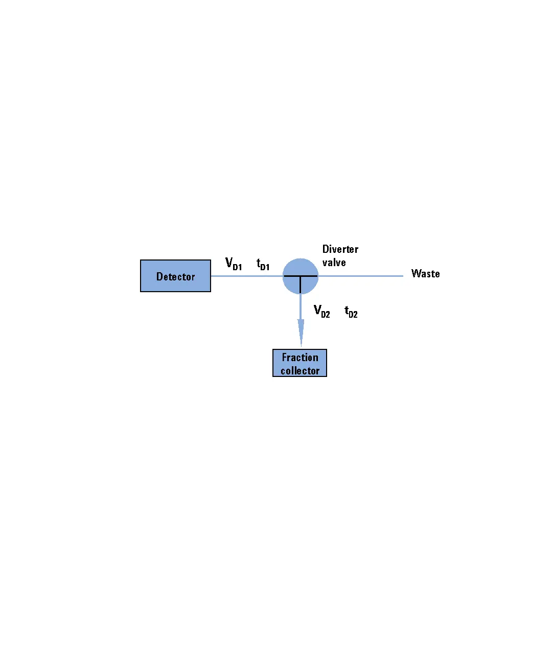
Figure 2 shows a schematic drawing of the fraction-collection part of the
Agilent 1100 series purification system with the two delay volumes V
D1
and
V
D2
. For peak-based fraction collection the system delay times t
D1
and t
D2
can
be calculated by dividing the delay volumes by the flow rate .
The delay volume V
D2
is a system constant and is 23 µl for the fraction
collector AS and 120 µl for the fraction collector PS. Delay volume V
D1
, which
is displayed in the Fraction Collector Configuration window, is determined
using the Delay Volume Calibration feature of the ChemStation software.
When a peak is detected during a purification run (Figure 3) the diverter valve
is triggered using the following delay time calculations:
Start of fraction collection: t = t
0
+ t
D1
End of fraction collection: t = t
E
+ t
D1
+ t
D2
Figure 2 Delay Volumes and delay times
ν

 Loading...