16 Agilent 1100 Series Fraction Collectors User’s Guide
1 Configuration and Operation of the Fraction Collector
Delay volumes and delay calibration
Detector signal delay
Every Agilent UV detector that is used for triggering fractions has an internal
signal delay caused by filtering the raw data. The signal delay depends on the
Peakwidth setting of the detector and is accounted for when the diverter valve
is triggered. Tables 1 and 2 show the internal signal delay times for different
Peakwidth settings
.
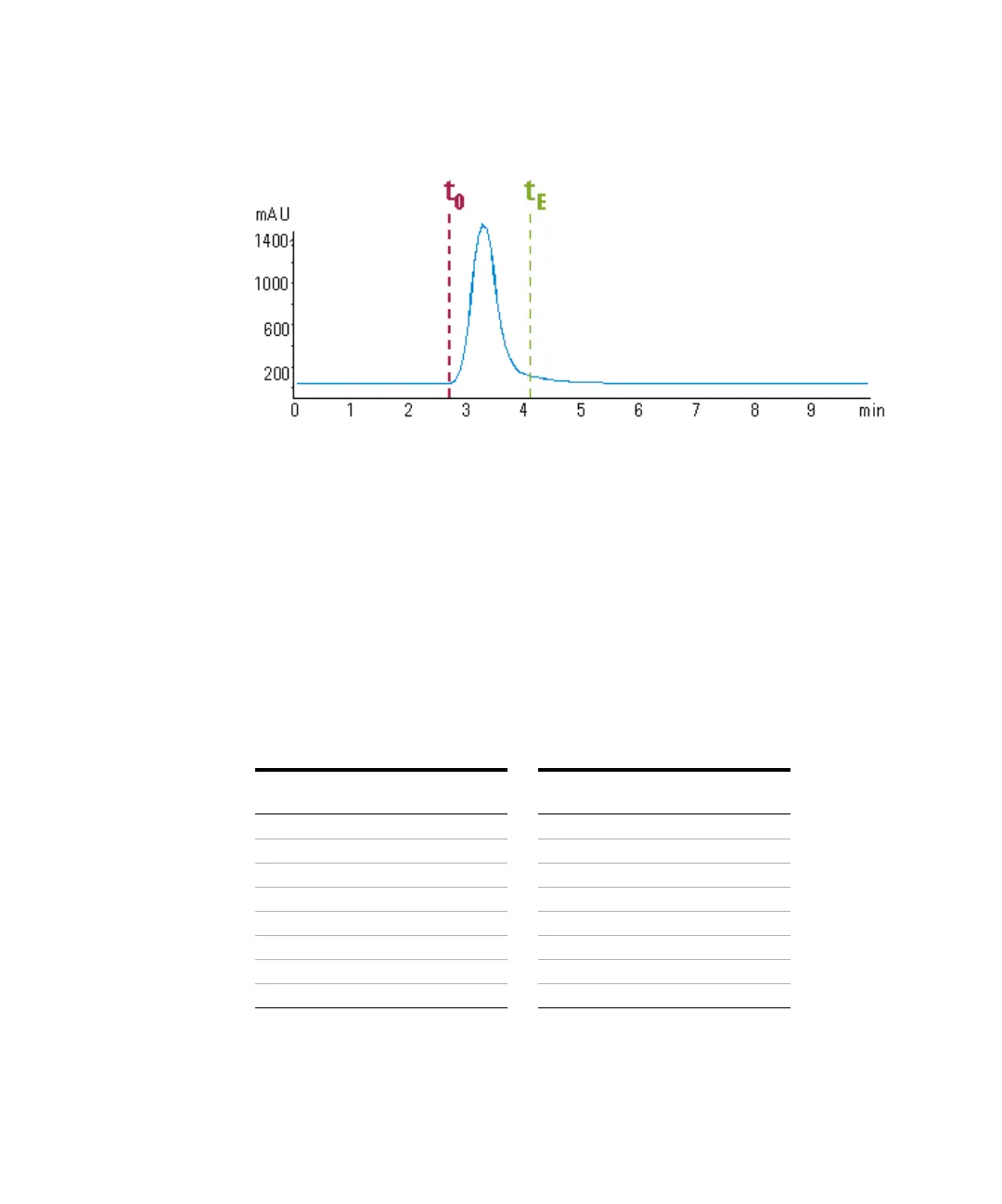
Figure 3 Chromatogram with peak start t0 and peak end tE
Table 2 DAD/MWD
Peakwidth
(min)
Response
time (sec)
Signal
delay (sec)
<0.01 0.1 0.05
>0.01 0.2 0.15
>0.03 0.5 0.5
>0.05 1.0 1.25
>0.10 2.0 2.75
>0.20 4.0 5.9
>0.40 8.0 11.9
>0.85 16.0 23.9
Table 3 VWD
Peakwidth
(min)
Response
time (sec)
Signal
delay (sec)
<0.005 <0.1 0.07
>0.005 0.12 0.14
>0.01 0.25 0.29
>0.025 0.5 0.58
>0.05 1 1.31
>0.1 2 2.84
>0.02 4 5.97
>0.4 8 12.3
 Loading...