4-32 Service Guide N5230-90024
Troubleshooting PNA Series Microwave Network Analyzers
Measurement System Troubleshooting N5230C
Checking the A7 Fractional-N Synthesizer Output, Band 3
Perform this procedure if you observe a problem in band 3 in all receivers.
1. Refer to the block diagram at the end of this chapter and to “Top Cables, All Options” on page 6-14.
Locate semirigid cable W1, at the A7 fractional-N synthesizer board.
CAUTION Be careful not to damage the center pins of the semirigid cable. Some flexing of the cables is
necessary to measure the output. Do not over bend them.
2. Using a 5/16 inch torque wrench, disconnect W1 at A7J106.
3. Connect the spectrum analyzer to A7J106.
4. Set the network analyzer to a CW frequency of 1 GHz.
• The spectrum analyzer should measure a signal at 1 GHz.
5. If this signal is not present, replace the A7 fractional-N synthesizer board. Refer to “Removing and
Replacing the A5 through A10 Boards and the Plenum Bracket” on page 7-16.
6. If the signal is present, leave the spectrum analyzer connected to A7J106 and continue with “Checking
the A7 Fractional-N Synthesizer Output, Bands 4 through 30” on page 4-32.
Checking the A7 Fractional-N Synthesizer Output, Bands 4 through 30
Perform this procedure if you observe a problem in bands 4 through 30 in all receivers.
1. Set the network analyzer to measure a CW frequency of 2 GHz.
• The spectrum analyzer should measure a signal at 2 GHz.
2. If the signal is not present, replace the A7 fractional-N synthesizer board. Refer to “Removing and
Replacing the A5 through A10 Boards and the Plenum Bracket” on page 7-16.
3. If the signal is present, reconnect cable W1, and then continue with “Checking the A6 Multiplier Output,
All Bands” on page 4-34.
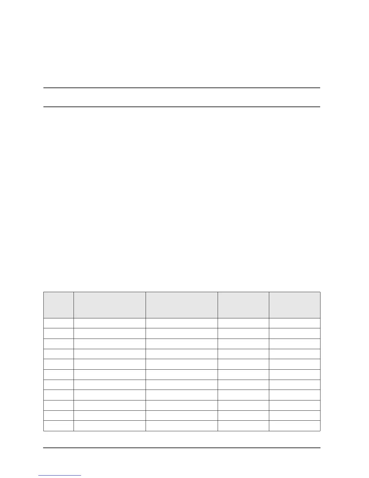
Table 4-4 LO Path Frequencies
Band
Network Analyzer
Frequency Band of Problem
(GHz)
Network Analyzer Source
Frequency Setting (GHz)
Expected A7
Output Frequency
(GHz)
Expected A6
Output Frequency
(GHz)
1 0.010 to 0.045 0.025 0.025 0.025
2 0.045 to 0.748 0.500 0.500 0.500
3 0.748 to 1.500 1.000 1.000 1.000
4 1.500 to 3.125 2.200 2.200 2.200
5 3.125 to 4.167 3.600 1.800 3.600
6 4.167 to 5.250 4.600 2.300 4.600
7 5.250 to 6.250 5.700 2.850 5.700
8 6.250 to 7.875 6.500 1.625 6.500
9 7.875 to 8.333 8.100 2.025 8.100
10 8.333 to 9.375 8.800 2.200 8.800
11 9.375 to 10.500 9.900 1.650 3.300

 Loading...


