S220/S221/S230/S231/Z2006-8
6 Attachments
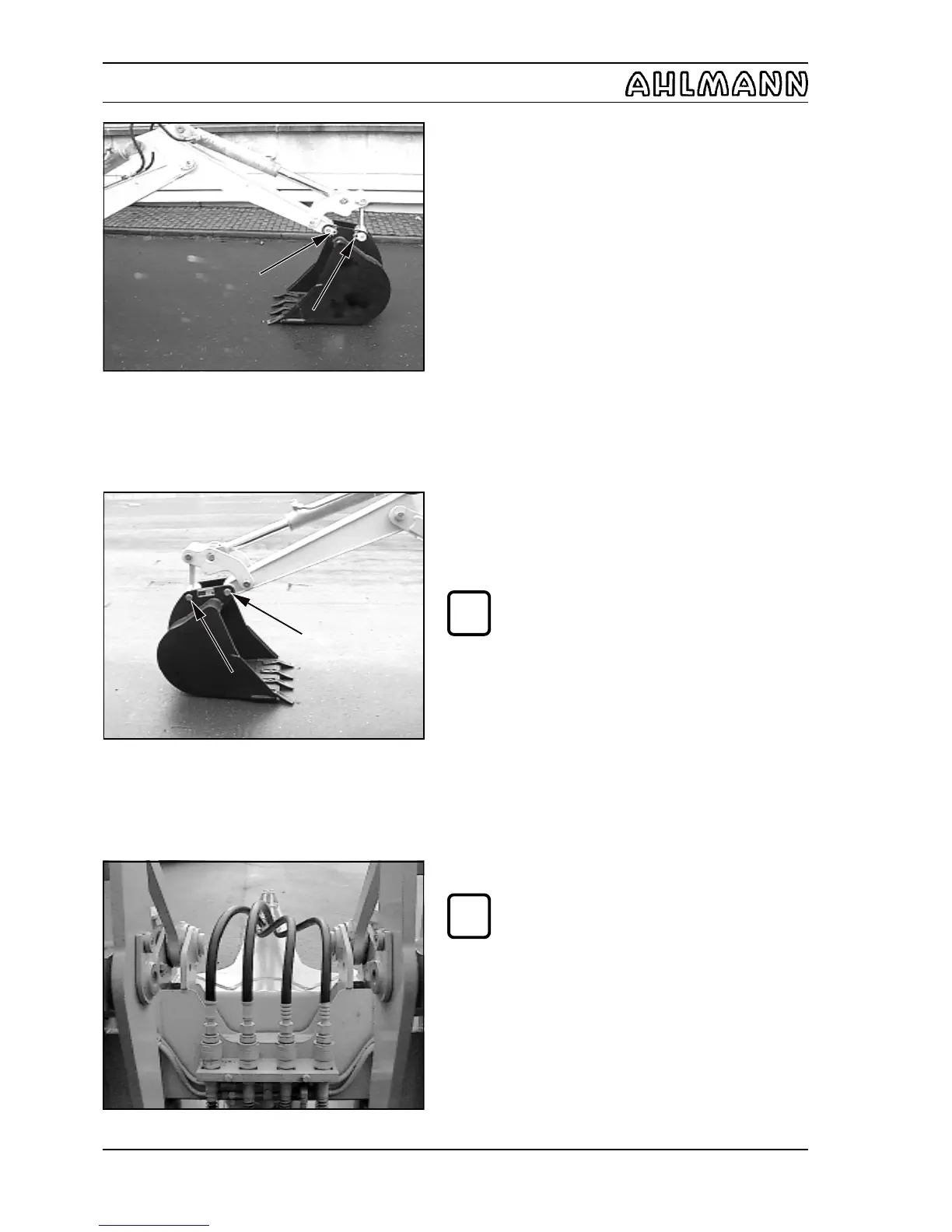
(5) Remove the spring locking lever of the bolt locks (6-18/
arrows).
(6) Knock out the bearing bolts (6-19/arrows) and remove
the shovel.
(7) Mounting is in the reverse order.
NOTE
The type plate of the shovel is on the left outer
side.
6.3.3 Grab bucket
NOTE
- The movements of the grab bucket can be
seen in the symbols of the sign for the
auxiliary hydraulic system.
- The grab bucket can be turned to the left or
right around its vertical axis without limits.
Mounting
The grab bucket is mounted in a manner similar to the
multi-purpose bucket (section 6.3.1), except that all four
hydraulic hoses of the grab bucket must be connected to
the four quick-change couplings of the quick-change device
(6-20).
Figure 6-18
Figure 6-19
Figure 6-20
i
i