S220/S221/S230/S231/Z2008-8
8 Maintenance
4
1
2
3
1
2
Figure 8-12a
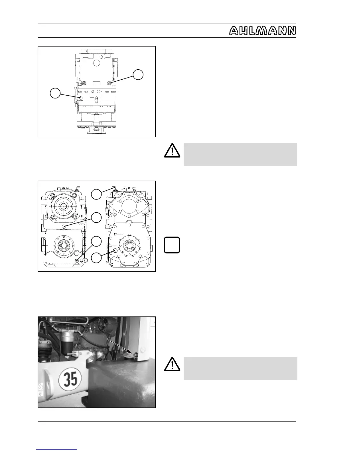
8.2.8 Oil change, distribution gear
(1) Remove the foot mat in the footwell of the operator’s
cabin.
(2) Dismantle the floor plate under the foot mat.
(3) Place a sufficiently large oil drain pan with a drain
channel underneath.
(4) Unscrew the filling (8-12/1 and 8-12/2) and drain plugs (8-
12a/2) and let oil drain from the upper oil compartment through
the drain channel.
(5) Unscrew the drain (8-12a/3) and inspection plugs (8-
12a/4) and drain the oil from the lower oil compartment.
CAUTION
Waste oil must be disposed of in such a way that
it will not cause pollution!
(6) Screw the drain plugs (8-12a/2 and 8-12a/3) back in
with new gaskets.
(7) Fill in oil through the filling plug bore of the upper oil
compartment (8-12/1) until the oil reaches the mark on the
dipstick (8-12a/1).
(8) Fill in oil through the filling plug bore of the lower oil
compartment (82/3) until the oil reaches the lower edge of
the oil inspection bore (8-12/4).
NOTE
Information about the quantities of oil is given in
the maintenance plan (chapter 8).
(9) Screw the filling (8-12/1 and 8-12/2) and inspection
plugs (8-12a/4) back in with new gaskets..
8.2.9 Oil change, hydraulic system
(1) Have an oil pan ready (at least 250 l).
(2) Open both engine flaps.
(3) Unscrew the covering flap of the oil drain plug (8-13/
arrow).
(4) Screw the drainage nozzle with hose from the tool box
(4-1/12) to the oil drain plug.
(5) Remove the cover cap from the hose.
(6) Drain the oil into the oil pan.
CAUTION
Waste oil must be disposed of in such a way that
it will not cause pollution!
(7) Remove the nozzle with the hose and replace the
cover cap on the hose.
(8) Screw the covering plate onto the oil drain plug.
(9) Replace the suction / return flow filter cartridge (section
8.2.10).
View from rear View from front
Figure 8-13
Plan view
Figure 8-12
i