S06C
S06C
4-1
4 Beskrivning
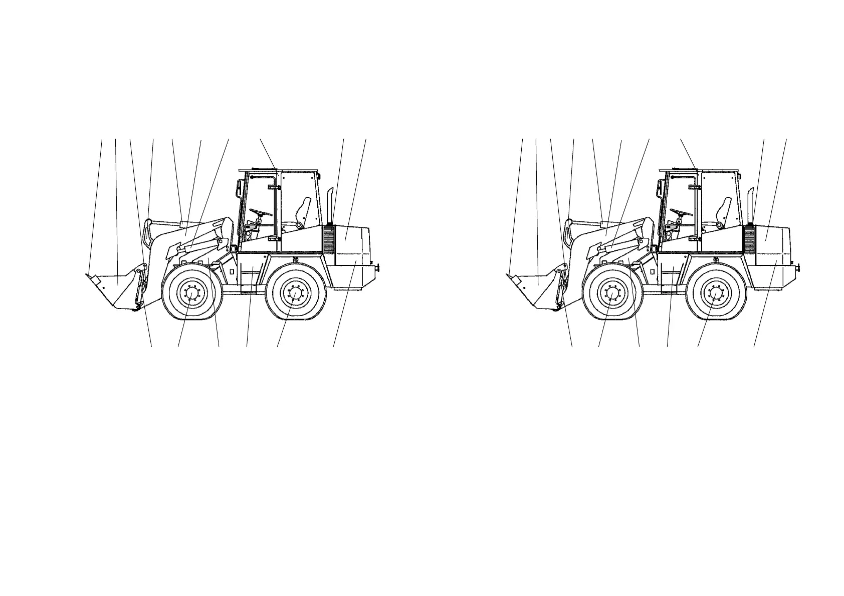
4.1 Översikt
Fig. 4-1
16 15 14 13 12 11
123 4 5 6 7 8 9 10
10 - Drivmotor
11 - Batterifack
(högra sidan på fordonet)
12 - Bakaxel
13 - Verktygslåda
14 - Vridbart säte
15 - Framaxel
16 - Snabbfäste
17 - Bränslebehållare, trappsteg
på fordonets högra sida (ej i
figur)
1 - Skopskydd
2 - Skopa/redskap
3 - Tipparm/tippstång
4 - Ledarm
5 - Tippcylinder
6 - Lyftarm
7 - Lyftcylinder
8 - Förarhytt
9 - Hydrauloljebehållare/
påfyllningsrör
4 Description
4.1 Component designation
Fig. 4-1
16 15 14 13 12 11
123 4 5 6 7 8 9 10
10 - Drive unit
11 - Battery compartment (right
hand side of vehicle)
12 - Rear axle
13 - Tool box
14 - Revolving seat
15 - Front axle
16 - Quick-change device
17 - Fuel tank, ladder right hand
side of vehicle(not shown)
1 - Bucket protection
2 - Bucket/attachment
3 - Tilt lever/tilt shaft
4 - Pivot arm
5 - Tip cylinder
6 - Bucket arm
7 - Lift cylinder
8 - Operator´s cabin
9 - Hydraulic oil reservoir/
filling cap