EasyManua.ls Logo

Aim ANET42 - Figure 2-3 37 Pol DSUB; Table 2-1 Front Panel Connector Pinout for 4 Channels

Default Icon
67 pages
Print Icon
To Next Page IconTo Next Page
To Previous Page IconTo Previous Page
Loading...
2. Installation
ANET429-x Users Manual
5
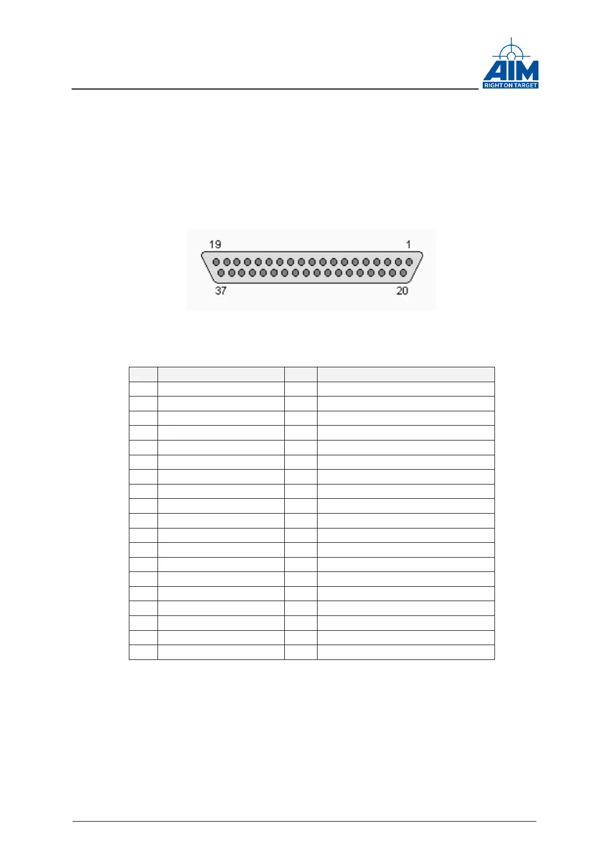
2.2.1.1 ARINC429 Interface Connectors
For connecting to the external ARINC429 Busses, a DSUB37 (female) connector is
used.
Depending to the number of channels the pin out of the connectors does slightly differ.
In the 4 and in the 8 channel Version the RX and TX channels are separate, whereas in
the 16 channel Version the RX and TX channels are combined.
The following pin assignments are used:
Figure 2-3 37pol DSUB
Pin
Signal Description
Pin
Signal Description
1
Tx Channel 1 (True)
20
Tx Channel 1 (Complement)
2
Tx Channel 2 (True)
21
Tx Channel 2 (Complement)
3
Tx Channel 3 (True)
22
Tx Channel 3 (Complement)
4
Tx Channel 4 (True)
23
Tx Channel 4 (Complement)
5
Reserved
24
Reserved
6
Reserved
25
Reserved
7
Reserved
26
Reserved
8
Reserved
27
Reserved
9
Trigger In 0
28
IRIG Out
10
Ground
Reserved
11
Trigger Out 0
29
IRIG In
12
Rx Channel 1 (True)
30
Rx Channel 1 (Complement)
13
Rx Channel 2 (True)
31
Rx Channel 2 (Complement)
14
Rx Channel 3 (True)
32
Rx Channel 3 (Complement)
15
Rx Channel 4 (True)
33
Rx Channel 4 (Complement)
16
Reserved
34
Reserved
17
Reserved
35
Reserved
18
Reserved
36
Reserved
19
Reserved
37
Reserved
Table 2-1 Front panel Connector Pinout for 4 Channels

Table of Contents

Related product manuals