5. Structure of the ANET429
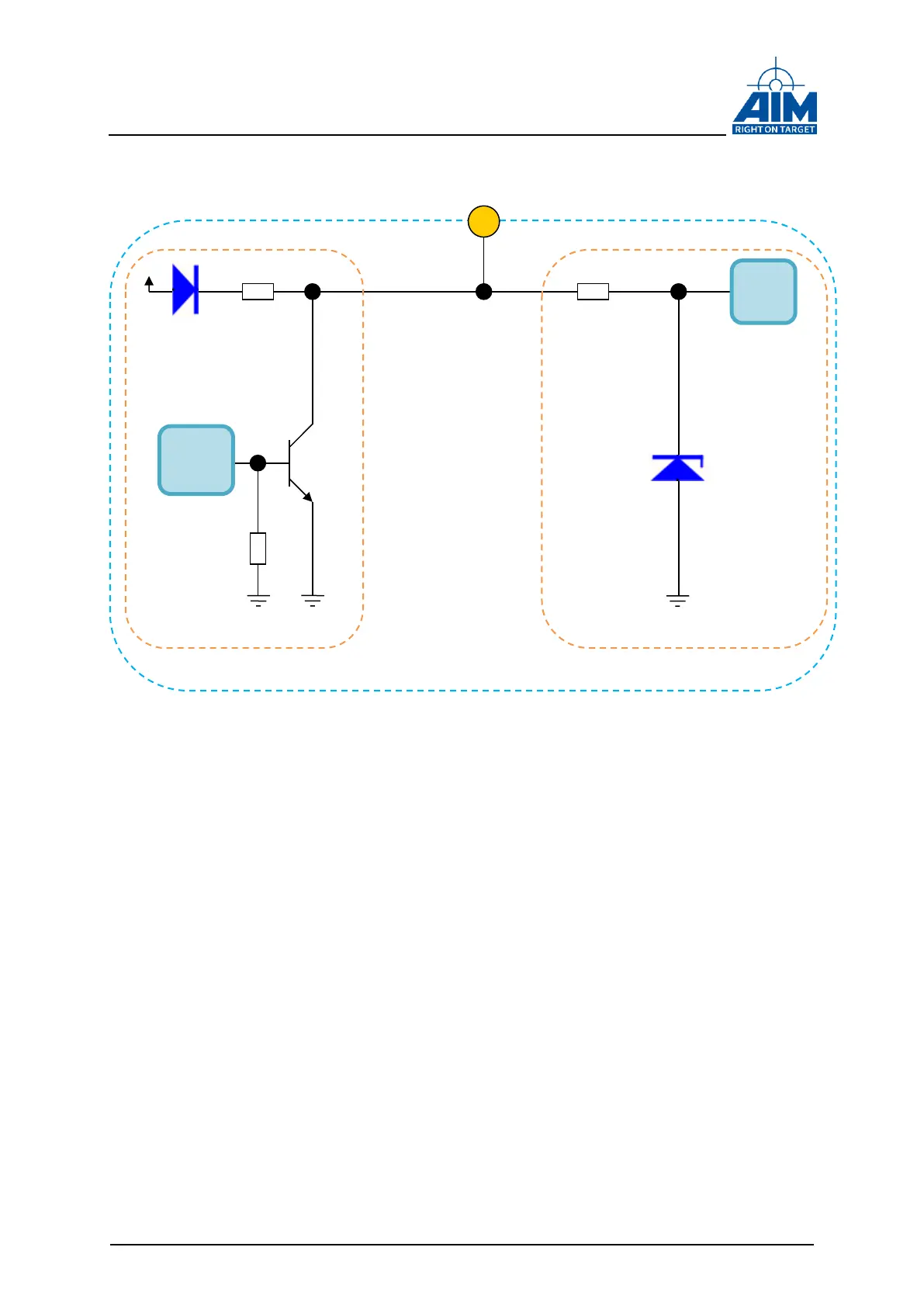
Figure 5-2 Discrete I/O circuitry
Be aware that a series resistor must be provided when a user voltage is used
(Figure 5-3 Discrete I/O-Pin off board user series resistor).
This serial resistor must limit the current through the open collector transistor to max.
current (see technical data chapter for details). Otherwise the open collector transistor
can be damaged. EMC aspects are covered by filter circuitry.
Discrete IO-Pin Front Connector
Resistor
limiting
Resistor
(1 KΩ)
limiting
Resistor
Discrete output circuitry