2.2.1.2 Auxiliary Connector HD DSUB15
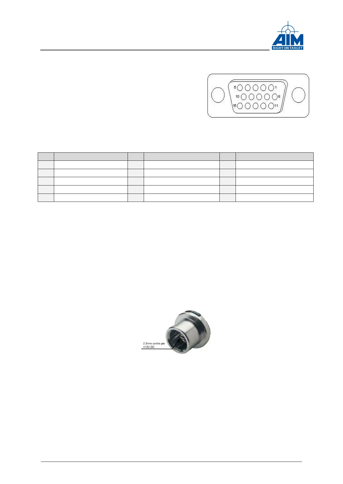
On the ANET429 a 15-pin female High Density
DSUB auxiliary connector is implemented for the
Trigger IN/OUT, IRIG IN/OUT and Discrete I/O
signals.
The figure on the right side shows the high density
DSUB connector.
The Table below shows the pin assignment.
A description of the Trigger IN/OUT, IRIG IN/OUT
and the Discrete IOs can be found later in this document.
Table 2-4 Pinout Auxiliary Connector
2.2.1.3 USB Type A Host connector
A Type A host USB connector is provided e.g. for connecting external storage devices
or an optional WLAN stick.
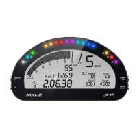
2.2.1.4 DC Power IN connector
The DC Power in plug is a DC panel socket with a 2,5mm centre pin.
The nominal input voltage is 12V DC via the centre pin.
Figure 2-5: DC panel socket
2.2.1.5 RJ45 Ethernet connector
For the Ethernet connection a standard RJ45 plug is provided at the back panel.
Figure 2-4 Auxilliary
Connector