FS2 v2.1r1 www.aja.com
108
Appendix B: FS2 Pinouts
GPI Pinouts
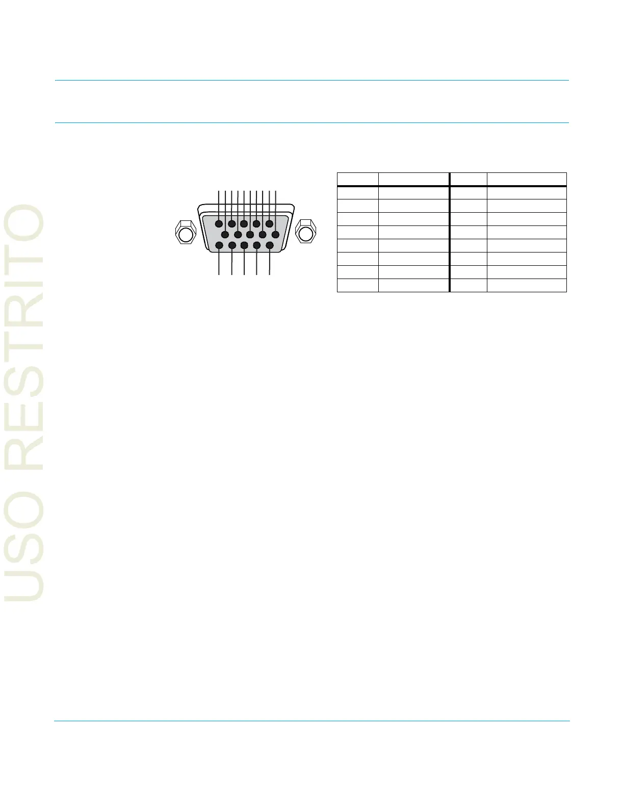
Figure 14. GPI DE-15F Connector Pinout
The GPI inputs and outputs are electrically iso
lated from power and ground on the FS2
frame. There are four inputs and four outputs. Electrical isolation is provided for up to
four pieces of external equipment.
The following guidelines apply to the f
our GPI inputs and outputs:
• GPI In 1 and GPI Out 1 share a common iso
lated ground on pin 5 (GPI GND 1),
• GPI In 2 and GPI Out 2 share a common iso
lated ground on pin 6(GPI GND 2).
• GPI In 3 and GPI Out 3 share a common iso
lated ground on pin 10(GPI GND 3).
• GPI In 4 and GPI Out 4 share a common isolated ground on pin 11 (GPI GND 4).
• Pins 1 and 15, local chassis ground, may only be used as references when isolation is
no
t required.
• All four GPI inputs are internally pulled high
through a 10K ohm resistor to an isolated
+5V supply, so that a relay contact closure or any device sinking at least 0.4 mA to
ground will register a logic low.
• All four GPI outputs are +5V TTL compatible, sourcing
up to 6mA and sinking up to
4mA each.
• GPI Inputs light the front p
anel EXT LED when triggered.
The following illustration shows typical external wiring to the GPI connector. The GPI
inputs r
equire some kind of contact closure between the input pin and the input ground
pin to register the logic low that triggers the GPI input.
You can connect the outputs to TTL buffers that communicate the GPI output logic levels
to
other devices. For example, you could use an opto-isolator controlling a relay to
activate other equipment as shown below.
1
15
11
5
6
10
Ground
GPI In 1
GPI In 2
GPI In 3
GPI GND 1
GPI GND 2
GPI In 4
GPI Out 1
GPI Out 2
GPI GND 3
GPI GND 4
GPI Out 3
GPI Out 4
NC
Ground
Pin Function Pin Function
1Ground 9GPI Out 2
2 GPI In 1 10 GPI GND 3
3 GPI In 2 11 GPI GND 4
4 GPI In 3 12 GPI Out 3
5 GPI GND 1 13 GPI Out 4
6GPI GND 214NC
7GPI In 4 15Ground
8GPI Out 1