7210 SAS-D Overview
7210 SAS-D Installation Guide Page 27
Power Switch
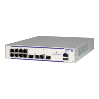
See Figure 13 on page 27 for the location of the power switch and Table 10 for key descriptions.
Figure 13: Location of the Power Switch
Table 9: 100/1000 Fiber-Optic SFP and 10/100/1000Base-T Copper Port LEDs
LED Condition Status
1/1/1 – 1/1/6 – SFP ports and
1/1/7 – 1/1/10 – Fixed
Copper ports
Green Port has a valid link.
Flashing Green Flashing indicates activity on the port.
Off The link is down.
Table 10: Front Panel Power Switch
Button/Switch Condition Status
Power Module Switch 0 Standby mode if switch is connected to a power source.
1 AC or DC power is applied to the switch.

 Loading...