Installing the 7210 SAS-D
7210 SAS-D Installation Guide Page 41
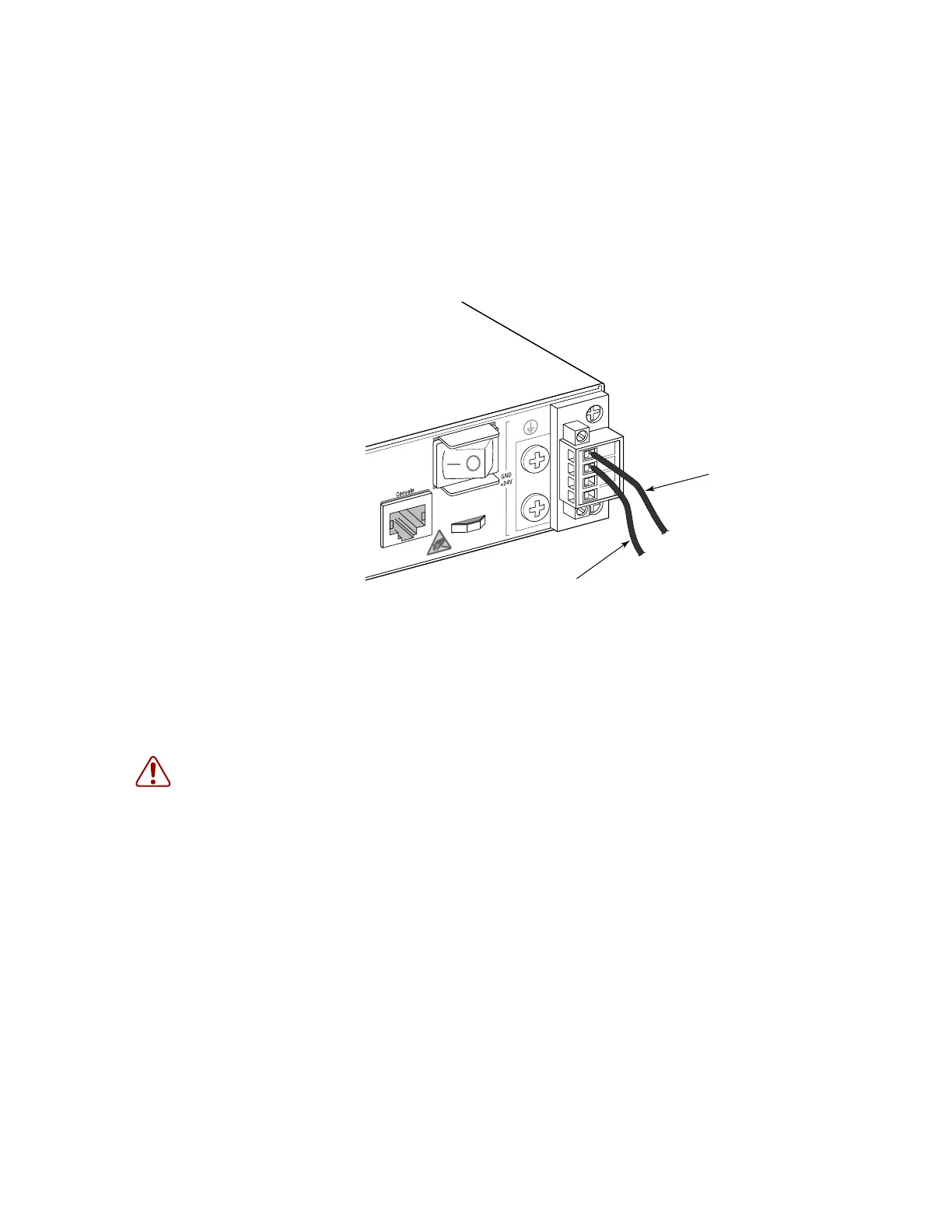
Step 4 Connect the +24 VDC power feed using the GND (ground) and +24 VDC
input lines. Insert the wires into the DC input plug (using a small flat-tip
screwdriver). Color code the wiring according to local standards to ensure
that the input power and ground lines can be easily distinguished. Figure 19
shows this step in greater detail:
Figure 19: Connecting a +24 VDC Power Source
Step 5 After the power source is tuned on, set the power button on the front of the
power supply module to the ON position (marked “— ').
Step 6 Check the power LED as the switch is powered on to verify that the LED
indicating external power status is on, and that the LED indicating internal
power conversion is on. If not, recheck the power source and power cable
connections at the supply source and at power supply module.
7210SASdc_0014
Ground (Pin 1)
+24V (Pin 2)
WARNING: If the power leads are plugged into the wrong holes, the power supply will not work
properly and may damage the switch.

 Loading...