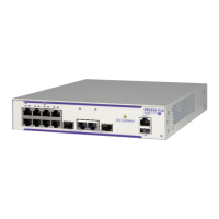
Installing Your Switch
Page 40 7210 SAS-D Installation Guide
Connecting to a +24 VDC Power Source
To connect the switch to a +24 VDC power source:
Step 1 Before a +24 VDC power supply module can be used, you must connect an
external DC power source to the DC power connection on the right side of the
front panel.
Step 2 To provide adequate circuit protection between the DC power source and the
switch, all intermediate wiring and circuitry should be rated to carry a load at
least two times the maximum rating for this switch (see "Appendix A:
Specifications" on page 79).
Step 3 The wiring between the DC power supply and the switch must be stranded
copper wire within the range of 10 to 24 AWG.
Note: Below the DC power entry block is an additional chassis ground point for attaching a
DC power chassis ground if required by local electrical codes. The ground point should be
connected with an M4 screw and a terminal lug as specified by local electrical codes.
WARNING: Although the system provides four inputs pins to connect a DC power source, use
the top two pins only. Pins 3 and 4 are not connected or recommended.
WARNING: Before wiring the DC plug or connecting power to the switch, ensure that power to
the feed lines is turned off at the supply circuit breaker or disconnected from the power bus.

 Loading...