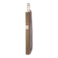
The safety/drain valve must not be mounted higher
than the hose connection.
NOTICE
Only use genuine Alde valves.
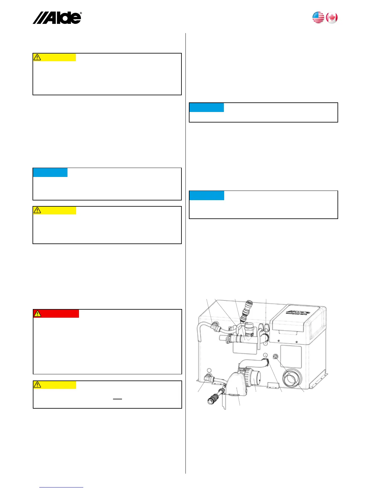
Figure D
22
21
29
27
28
23
24
26 25
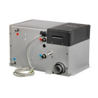
CONNECTION TO THE
HEATING SYSTEM
TheLPGasboiler’sconnectionpipetotheheating
systemislocatedonthesideoftheboiler.Theredmark-
ingisforoutgoingowpipe(D21)andthebluemarking
isforincomingreturnpipe(D22).Usetheassemblyset
withautomaticbleederandautomaticcirculationstopfor
mountingontheboiler.Connecttheout-goingpipewith
therubberTpipe(D23).Thedraininghose(D27)from
thebleedershallgooutthroughtheoorofthevehicle.
Thehoseshallbecutobliquelyata30°anglefromthe
directionoftravel.
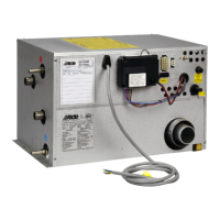
CONNECTION TO THE FRESH-WATER
SYSTEM
Theboilermustbeconnectedtothevehicle’sfreshwater
systeminordertofunction.Thefreshwaterconnections
areonthesideoftheboiler.Thebluemarkingindicates
incomingcoldfreshwaterandtheredmarkingindicates
outgoinghotwater.
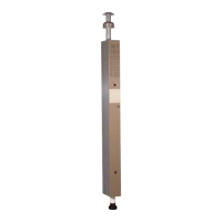
EXTERNAL SAFETY VALVE WITH
BUILT-IN DRAIN
AldeArticleNo.3010431Safety/Drainvalve(seeFigure
D24)shallbemountedonthecoldwaterhoseintothe
heater.DrillaØ3/4inch(16mm)holeintheoorforthe
drainhose,andthenscrewdownthesafety/drainvalve
intotheoor.Mountthehoseconnection(SeeFigure
D26)ontheincomingnipple.Connectthesafety/drain
valvetothehoseconnection.
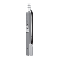
Mounttheangleconnectionwithbuilt-inbleedvalveon
outgoingconnection(SeeFigureD28).Thisshallbe
mountedinthesamewayasthehoseconnection.Mount
thebleedhose(FigureD28)onthevalve’shosesleeve,
andthenpullthehoseoutthroughtheoor.Thehose
shallbecutobliquelyata30°anglefromthedirectionof
travelunderthevehicle.Thehosemustnotbeblocked.
CONNECTING THE LP GAS
Removetheprotectivecapfromthegaspipeonthe
boiler(F29).MaketheLPGasinstallationtotheboiler
witha3/8inchareconnection.Whenlayingthepipe,
rememberthattheboilerhastobedismountedforser-
vice.TheboilershouldbeconnectedtoanLPgascyl-
inderwithtype-approvedpressurereducingvalveanda
pressureof30mbar.
NOTICE
Current national regulations must be adhered to
when installing LP gas.

 Loading...