22
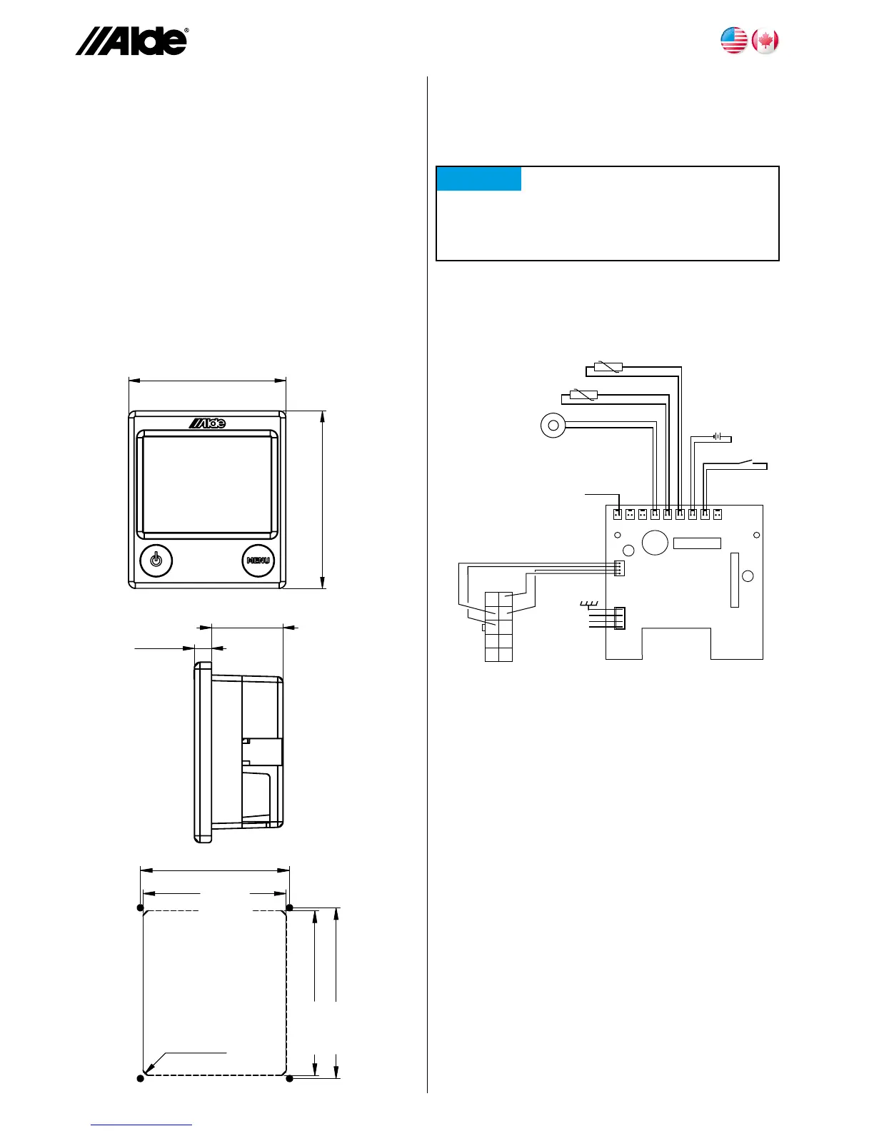
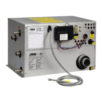
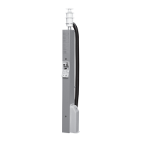
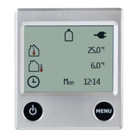
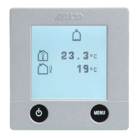
ControlPanel3010614isintendedfortheAldeCompact
3010boiler.
TheControlPanelshouldbelocatedatleast3,3foot(1
meter)abovetheoor,butnottooclosetotheceiling.
Norshoulditbeenclosed,locatedonanouterwallor
closetoobjectswhichradiateheat,forexample,CDplay-
ers,refrigeratorandlamps,asthiscangiveincorrecttem-
perature.Theareabehindthepanelshouldbewellven-
tilated.Iftheroomtemperatureonthepanelisaffected
nevertheless,anexternalsensorshouldbeconnectedto
thepanel.
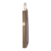
MakeaholeforthepanelasshowningureC.Screw
downthepanelandpushthefrontparton.Cliponthe
cablestoavoidwearontheterminalstripofthepanel.
A.
86 mm
97 mm
3,5”
3,8”
9 mm
38,5 mm
3,5”
1,5”
84 mm
73 mm
R3(4x)
76 mm
87 mm
3”
2,8”
3,3”
3,4”
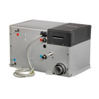
CABLE CONNECTION
CONTROL PANEL 3010 614
ConnectaccessoriestotheControlPanelasshowninthedia-
grambelow.
Windowbreaker
(I)
Back of Control Panel
blue
1
2
3
4
5
6
7
8
9
10
+
B
JP6
JP4
JP1
R30
BZI
EXT
E F (G) (H) I
C8
C23
+
Remotesensor,white(G)
red
Pumpsignal(B)
Loadmonitor,green(E)
Externalsensor,blue(F)
black
red
grey
BatteryBack-up
(3VDC)(H)
INSTALLATION INSTRUCTIONS
CONTROL PANEL 3010 614
C.
B.
NOTICE
Do not clamp or bind 12 V cables or sensor cables
together with 120 V cables. It is preferable not to
place the cables close to each other. If the cables
are bundled, the risk of shutdown increases.