262 Rockwell Automation Publication MOTION-RM003I-EN-P - February 2018
Drive Model Time Constant
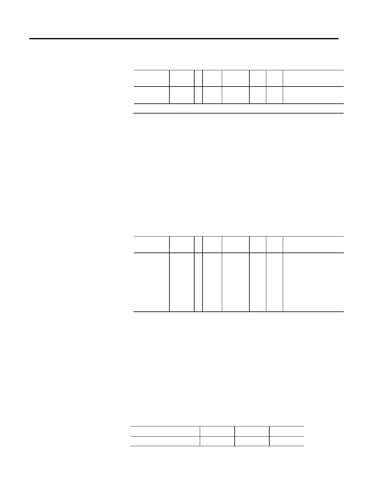
Usage Access T Data
Type
Default Min Max Semantics of Values
Required - C
Set/
SSV#
REAL 0.0015
FD
10
-6
1 Seconds
# Indicates the attribute cannot be set while the tracking command (Tracking Command bit in CIP Axis Status is true).
The value for the Drive Model Time Constant represents a lumped model time
constant for the drive's current loop and is used to calculate the Velocity and
Position Servo Bandwidth values. The Drive Model Time Constant is the sum of
the drive's current loop time constant, the feedback sample period, calculation
delay, and the time constant associated with the velocity feedback filter. This value
is set by software based on the specific drive amplifier and motor feedback
selection.
Since the bandwidth of the velocity feedback filter is determined by the resolution
of the feedback device, the value for the Drive Model Time Constant is smaller
when high resolution feedback devices are selected.
Application Type
Usage Access T Data
Type
Default Min Max Semantics of Values
Required - PV Set/GSV
USINT 1 - - Enumeration:
0 = Custom
1 = Basic
2 = Tracking
3 = Point-to-Point
4 = Constant Speed
5-255 = Reserved
This attribute specifies the type of motion control application and is used by
configuration and auto-tune software to set the Gain Tuning Configuration Bits
attribute that establishes the appropriate gain set the application.
The relationship between Application Type and Gain Tuning Configuration Bits
is described in the following tables.
The first table shows which Integrator Bandwidth values are applicable based on
the Application Type. Separate bits are defined in the Gain Tuning Configuration
Bits attribute to enable tuning of Position Integrator Bandwidth, Kpi, and
Velocity Integrator Bandwidth, Kvi. The Integrator Hold, iHold, setting applies
to any active integrators.
Application Type Kpi Kvi iHold
Custom - - -

 Loading...


