286 Rockwell Automation Publication MOTION-RM003I-EN-P - February 2018
1. Ramp Decel
2. Current Limit Decel
3. Coast
In general, the "best" stopping action is the most controlled deceleration method
still available given the exception condition.
The final state of the power structure in response to the Major Fault exception
action can be any one of the following states that are listed in decreasing levels of
control functionality:
1. Hold (stopped with Holding Torque)
2. Disable (stopped with Power Structure Disabled)
3. Shutdown (stopped with Shutdown Action)
The "best" final state of the power structure is the state with the most control
functionality still available given the exception condition.
In all these final states a fault reset must be executed before the axis can be restored
to enabled operation and commanded to move.
If a Start Inhibit condition is present at the time of the exception, the best final
state for the exception action can only be Disable or Shutdown.
The specific stopping action and final state associated with a given Stop Drive
exception action is captured in the Axis Fault Action attribute that is included in
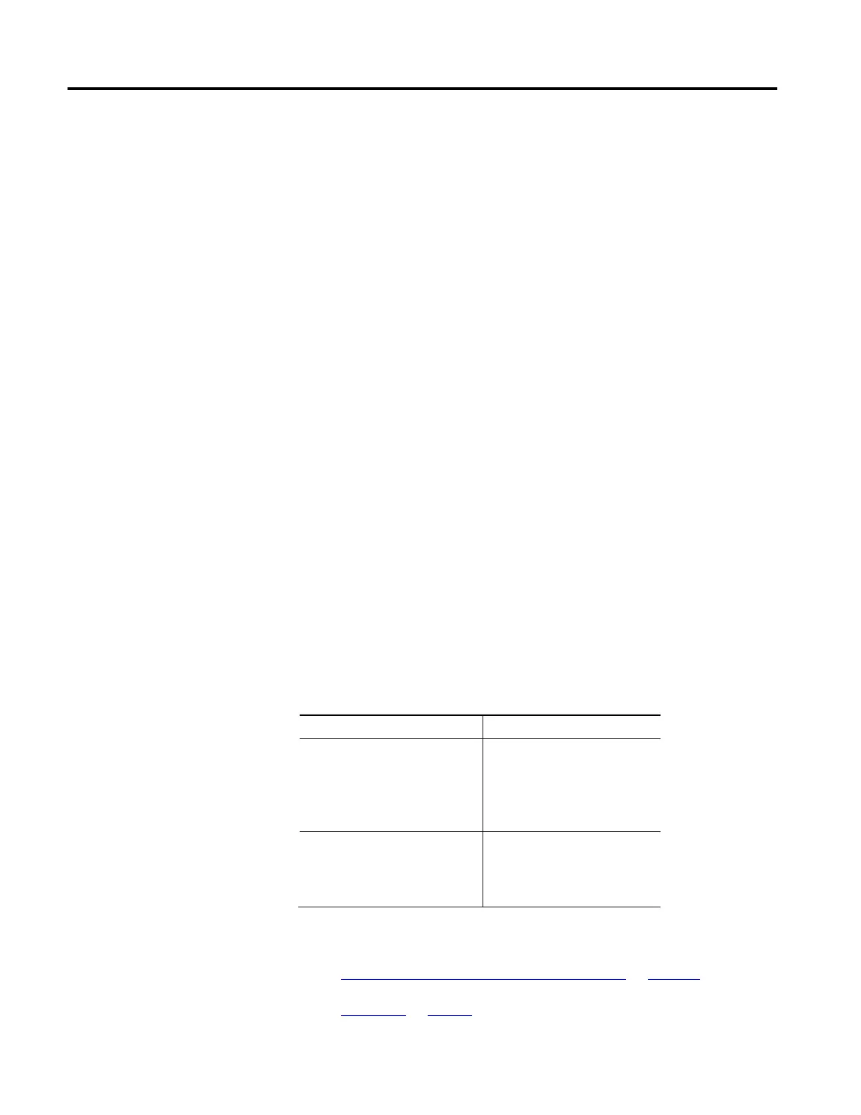
the Fault Log record. Axis Fault Action enumerations are as follows:
Enumeration Description
Stop Action Enumerations 0 = No Action
1 = (reserved)
2 = Ramped Stop
3 = Torque Limited Stop
4 = Coast
State Change Enumerations 0 = No Action
1 = Hold
2 = Disable
3 = Shutdown
See also
Axis Exception Action Configuration Attributes on page 281
Exceptions on page 41

 Loading...


