Rockwell Automation Publication MOTION-RM003I-EN-P - February 2018 359
Homing Sequence Types Description
Active Bidirectional Home to
Switch
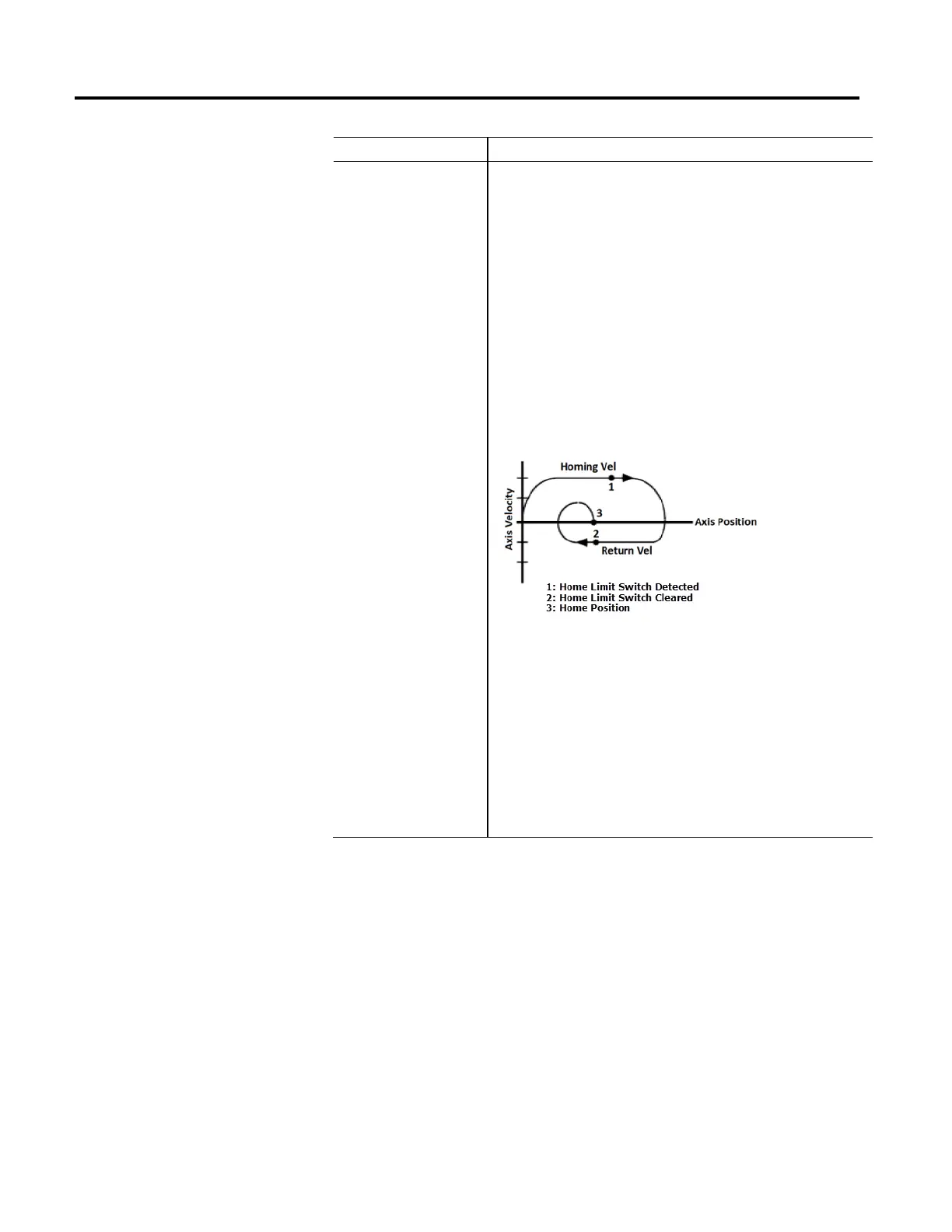
This active homing sequence is useful when an encoder marker is not available. When
this sequence is performed, the axis moves in the specified Home Direction at the
specified Home Speed and Home Acceleration until the home limit switch is detected.
The axis then decelerates to a stop at the specified Home Deceleration and then moves
in the opposite direction at the specified Home Return Speed and Home Acceleration
until the home limit switch is cleared.
When the home limit switch is cleared, axis position is immediately redefined to be
equal to the Home Position and the axis decelerates to a stop at the specified Home
Direction.
If Home Offset is non-zero, then the Home Position will be offset from the point where
the home switch is cleared by this value. Once the axis decelerates to a stop at the
specified Home Deceleration, the controller then moves the axis back to the Home
Position at the Home Return Speed and Home Acceleration using a trapezoidal move
profile.
If the axis is configured in Cyclic Travel Mode, the move back to the Home Position takes
the shortest path, for example, no more than ½ revolution. The axis behavior for this
active homing sequence is depicted in the following diagram:
If the controller detects that the state of the home switch at the start of the homing
sequence is active, the controller immediately reverses the homing direction and
begins the return leg of the homing sequence.
Neglecting the mechanical uncertainty of the home limit switch, the accuracy of this
homing sequence depends on the time uncertainty in detecting the home limit switch
transitions. The position uncertainty of the home position is the product of the
maximum time for the control to detect the home limit switch (~10 milliseconds) and
the specified Home Return Speed. For this reason, the Home Return Speed is often
made significantly slower than the Home Speed.
For example, if a Home Return Speed of 0.1 inches per second (6 IPM) is specified, the
uncertainty of the home position is calculated as shown below:
Uncertainty = 0.1 Inch/Sec * 0.01 Sec = 0.001 Inch.

 Loading...


