394 Rockwell Automation Publication MOTION-RM003I-EN-P - February 2018
Motor Rated Peak Current
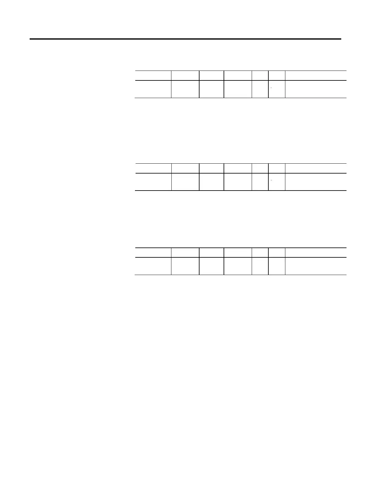
Usage Access Data Type Default Min Max Semantics of Values
Required - PM
Optional - IM
Set/GSV REAL 0
DB
0
Amps (RMS)
The Motor Rated Peak Current attribute is a floating point value that specifies the
peak or intermittent current rating of the motor. The peak current rating of the
motor is often determined by either the thermal constraints of the stator winding
or the saturation limits of PM motor magnetic material.
Motor Rated Output Power
Usage Access Data Type Default Min Max Semantics of Values
Required - IM
Optional - PM
Set/GSV REAL 0
DB
0
Power Units
The Motor Rated Output Power attribute is a floating point value that specifies
the nameplate rated output power rating of the motor. This represents the power
output of motor under full load conditions at rated current, speed and voltage.
Motor Overload Limit
Usage Access Data Type Default Min Max Semantics of Values
Optional Set/GSV REAL 100
DB
0 200
DB
% Motor Rated
The Motor Overload Limit attribute is a floating point value that specifies the
maximum thermal overload limit for the motor. This value is typically 100%,
corresponding to the power dissipated when operating at the continuous current
rating of the motor, but can be significantly higher if, for example, cooling options
are applied. How the Motor Overload Limit is applied by the drive depends on the
overload protection method employed.
For induction motors, this attribute is often related to the Service Factor of the
motor. The Service Factor is defined in the industry as a multiplier which, when
applied to the rated power or current of the motor, indicates the maximum power
or current the motor can carry without entering an overload condition.
Regardless of the Motor Type, if the drive applies an I
2
T motor overload
protection method, then exceeding the specified Motor Overload Limit results in
an overload condition and activates I
2
T overload protection. While the motor is
overloaded, the Motor Capacity attribute value increases to indicate how much of
the motor's available I
2
T overload capacity has been utilized. When Motor
Capacity reaches 100% of its rated capacity, the drive can optionally trigger a
Motor Overload Action.

 Loading...


