432 Rockwell Automation Publication MOTION-RM003I-EN-P - February 2018
• In the case of a Disable Request, the stopping method is applied while in the
Stopping state and the final state after the stopping method is completed is
the Stopped state.
• In the case of an Abort Request, the stopping method is applied while in the
Aborting state and the final state after the stopping method completes is the
Major Faulted state.
In either final state the device's inverter power structure will either be Disabled
(Disable selection) and free of torque or actively held (Hold selection) in a static
condition. This attribute has no impact or relationship to the planner generated
acceleration and deceleration profiles. This attribute does not, in any way,
determine the stopping actions applied in response to fault conditions.
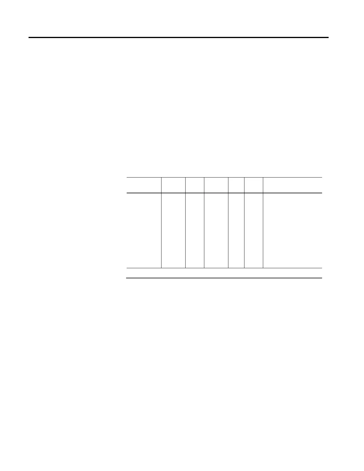
Connection Loss Stopping Action
Usage Access Data
Type
Default Min Max Semantics of Values
Optional - D
Set/
SSV#
USINT FD
1 for C
0 for F
- - 0 = Disable and Coast
1 = Current Decel and Disable
2 = Ramped Decel and Disable
3 = Current Decel and Hold
4 = Ramped Decel and Hold
5...127 = Reserved
128...255 = Vendor Specific
# Indicates the attribute cannot be set while the tracking command (Tracking Command bit in CIP Axis Status is true).
When a CIP Motion connection loss is detected, this value determines the
stopping method to apply to the motor. Each supported Stopping Action initiates
the associated Stopping Sequence (IEC60204-1 Category Stops 0, 1, and 2). If the
connection is closed intentionally using a Forward Close service, the selected
stopping method is applied while in the Stopping state and the final state after the
stopping method completes is the Initializing state. If the connection is
unintentionally lost and the resulting Node Fault generated, the selected stopping
method is applied while in the Aborting state and the final state after the stopping
method completes is the Major Faulted state. In either final state the device’s
inverter power structure will either be Disabled (Disable selection) and free of
torque or actively held (Hold selection) in a static condition.

 Loading...


