Rockwell Automation Publication MOTION-RM003I-EN-P - February 2018 433
Connection Loss Stopping Action
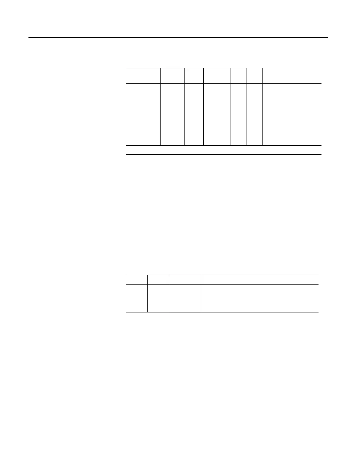
Usage Access Data
Type
Default Min Max Semantics of Values
Opt - D
Set/
SSV#
USINT FD
1 for C
0 for F
- - Enumeration:
0 = Disable and Coast
1 = Current Decel and Disable
2 = Ramped Decel and Disable
3 = Current Decel and Hold
4 = Ramped Decel and Hold
5-127 = (reserved)
128-255 = (vendor specific)
# Indicates the attribute cannot be set while the tracking command (Tracking Command bit in CIP Axis Status is true).
When a CIP Motion connection loss is detected, this value determines the
stopping method to apply to the motor. Each supported Stopping Action initiates
the associated Stopping Sequence (IEC60204-1 Category Stops 0, 1, and 2). If the
connection is closed intentionally using a Forward Close service, the selected
stopping method is applied while in the Stopping state and the final state after the
stopping method completes is the Initializing state. If the connection is
unintentionally lost and the resulting Node Fault generated, the selected stopping
method is applied while in the Aborting state and the final state after the stopping
method completes is the Major Faulted state. In either final state the device's
inverter power structure will be either Disabled (Disable selection) and free of
torque or actively held (Hold selection) in a static condition.
Stopping Action Enumeration Definitions
Enum. Usage Name Description
0 R/D
Disable and
Coast
Disable and Coast immediately disables the device power structure
and active control loops, which causes the motor to coast unless
some form of external braking is applied. This is equivalent to an
IEC-60204-1 Category 0 Stop.

 Loading...


