Rockwell Automation Publication MOTION-RM003I-EN-P - February 2018 435
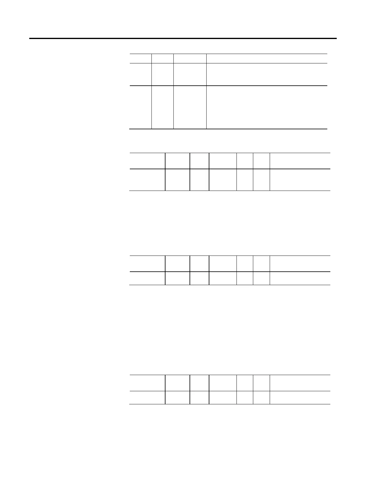
Enum. Usage Name Description
128 O/D
DC Injection
Brake
DC Injection Brake immediately applies the configured DC Injection
Brake Current to the motor to create a static flux field to bring an
induction motor to a stop before disabling the power structure.
129 O/D
AC Injection
Brake
AC Injection Brake decreases the device output frequency from its
present value to zero at the rate determined by the configured
Deceleration Limit. Stopping action is accomplished by lowering the
output frequency below the motor rotor speed where regeneration
does not occur and instead mechanical energy is dissipated in the
motor as heat.
Stopping Torque
Usage Access Data
Type
Default Min Max Semantics of Values
Required - C Set/SSV REAL 100
FD
0 10
3
% Motor Rated
When disabling or aborting an axis, this value determines the maximum amount
of torque producing current available to stop the motor when the Stopping Action
is set to Current Decel. If this attribute is not supported, the drive device will use
the configured Positive and Negative Peak Current Limits.
Stopping Time Limit
Usage Access Data
Type
Default Min Max Semantics of Values
Optional - D Set/SSV REAL 1 0 10
3
Seconds
When disabling or aborting an axis, this parameter determines the maximum
amount of time the drive allows to reach zero speed as part of the Category 1 or
Category 2 Stop sequence. Action taken by the drive once the time limit is reached
depends on the Stop Category. For a Category 1 Stop, the drive continues to apply
Stopping Torque while engaging the brake. For a Category 2 Stop the drive
continues to apply Stopping Torque but does not engage the brake. If Stopping
Time Limit is not supported a factory set timeout may be applied.
Coasting Time Limit
Usage Access Data
Type
Default Min Max Semantics of Values
Optional - D Set/SSV REAL 0 0 10
3
Seconds
When disabling or aborting an axis, this parameter determines the maximum
amount of time the drive allows to reach zero speed as part of the Category 0
"Disable and Coast" Stop sequence. Action taken by the drive if the time limit is
reached is to engage the brake and advance to the Stopped state. If this attribute is

 Loading...


