436 Rockwell Automation Publication MOTION-RM003I-EN-P - February 2018
not supported, the Coasting Time Limit applies the Stopping Time Limit value. If
Stopping Time Limit is not supported a factory set timeout may be applied.
Resistive Brake Contact Delay
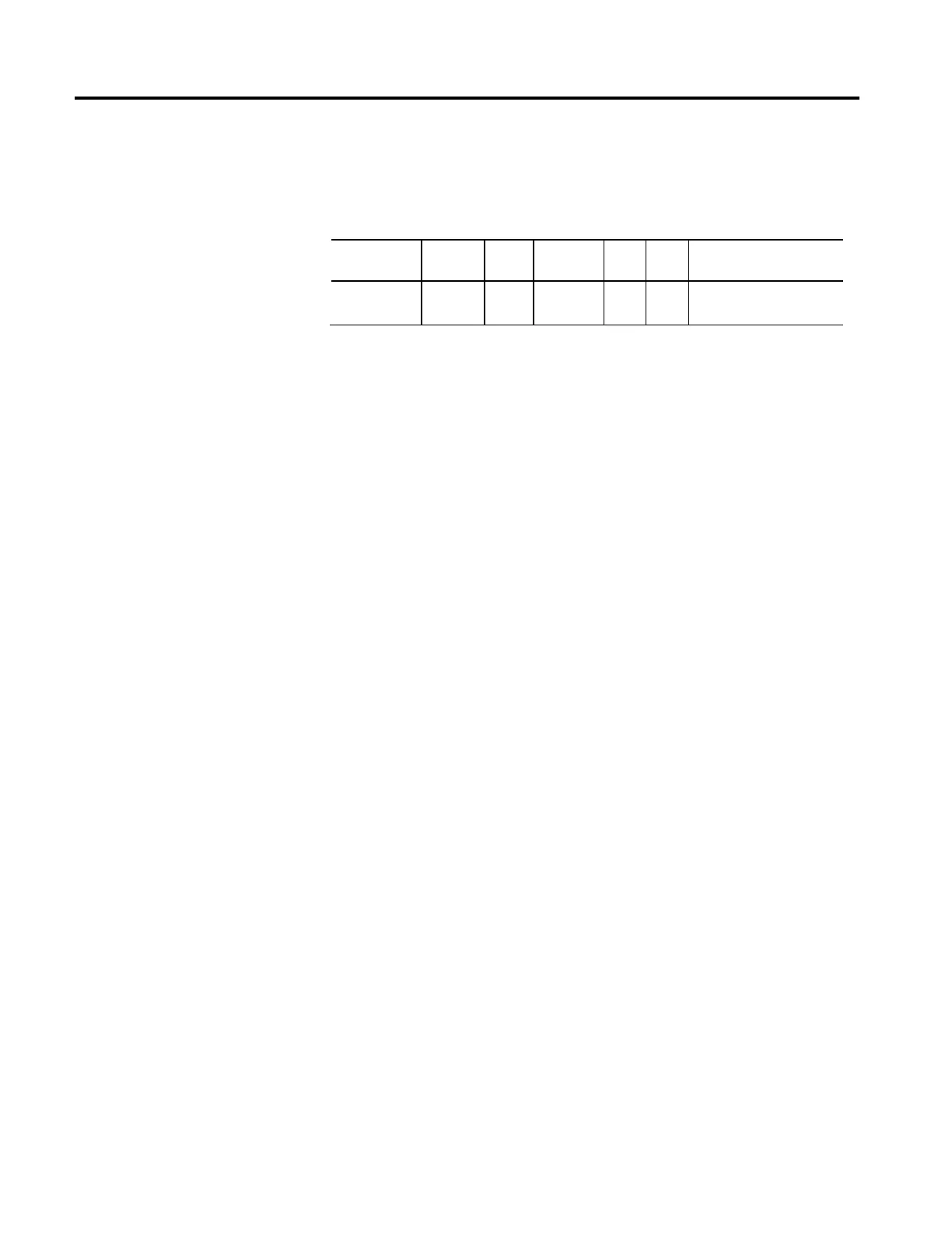
Usage Access Data
Type
Default Min Max Semantics of Values
Optional - D
(PM)
Set/SSV REAL 0 0 10
3
Seconds
When an external resistive brake is used, the Resistive Brake Contact Delay can be
set to delay the enabling of the device power structure until after the resistive
brake has had time to connect the motor to the drive device. When an external
resistive brake is used, an external contactor switches the UVW motor leads from
the inverter power structure to an energy dissipating resistor to stop the motor.
Note that this switching does not occur instantaneously and so enabling the power
structure too early can cause electrical arcing across the contactor. To prevent this
condition, the Resistive Brake Contact Delay can be set to the maximum time that
it takes to fully close the contactor across the UVW motor lines so when the axis is
enabled, the inverter power structure is not enabled until after the Resistive Brake
Contact Delay Time has expired. Resistive Brake operation is only applicable to
PM Motor types.
The following sequence further defines how the Resistive Brake Contact Delay
factors into the overall Enable Sequence that may also include the operation of a
Mechanical Brake.
Enable Sequence:
1. Switch to Starting state.
2. Activate Resistive Brake contactor to connect motor to inverter power
structure.
3. Wait for "Resistive Brake Contact Delay" while Resistive Brake contacts
close.
4. Enable inverter power structure.
5. Activate Mechanical Brake output to release brake.
6. Wait for "Mechanical Brake Release Delay" while brake releases.
7. Transition to Running state.

 Loading...


