Module Configuration Attributes
Rockwell Automation Publication MOTION-RM003I-EN-P - February 2018 477
Bus Regulator Action
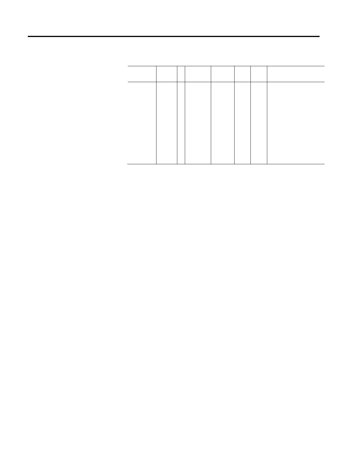
Usage Access T Data Type Default Min Max Semantics of Values
Optional - BD Set
USINT[8] []=1 - - Enumeration:
0 = Disabled O)
1 = Shunt Regulator (O)
2-127 = (reserved)
128 - 255 = (vendor specific)
Rockwell Automation
128 = Adj. Frequency (O/IM)
129 = Both – Shunt first (O/IM)
130 = Both – Freq first (O/IM)
131 = Bus Follower (O)
This 8-element array controls the method of operation of the DC Bus Regulator
that addresses the regenerative over-voltage conditions that can occur when
decelerating a motor associated with a given axis instance.
• "Disabled" specifies that no regulation is applied to the DC Bus level by this
device to control regenerative energy sourced by the motor.
• "Shunt Regulator" method applies the associated shunt regulation hardware
to the DC Bus to dissipate regenerative energy through an internal or
external resistor.
When controlling Induction Motors, additional bus regulation methods are
available that don’t require a shunt regulator.
• "Adjust Frequency" method controls the output frequency of the device
relative to the speed of the motor to control the amount of regenerative
energy pumped into the DC Bus.
• "Both - Shunt first" and "Both - Freq first" methods allow for different
sequential application of shunt regulation and frequency control to be
applied to the motor.
• "Bus Follower" method indicates that the DC Bus is generated by an
external converter rather than an integral converter. No bus regulation is
applied to the DC Bus level and the drive does not generate an exception if
the DC Bus is still active when the DC Bus contactor of the integrated
converter is open. In this context, the integral converter is not connected to
AC power.
Note that each drive instance in a multi-axis drive module can have an
independently configured Bus Regulator Action. The indexed elements of this
array correspond to axis instances 1 thru 8. Individual elements of this attribute

 Loading...


