48 Rockwell Automation Publication 2097-UM002D-EN-P - April 2017
Chapter 3 Kinetix 350 Drive Connector Data
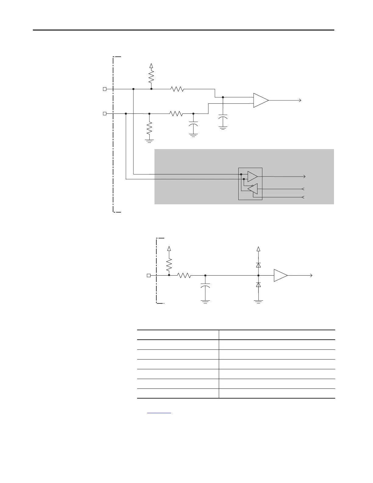
Figure 24 - Generic TTL Interface, IM Signals
Figure 25 - Generic TTL Interface, S1, S2, or S3 Signals
Table 22 - Tamagawa 17-bit Serial Specifications
See Figure 22 for the Tamagawa 17-bit serial interface schematic. It is identical
to the Stegmann Hiperface (DATA) signals schematic.
+
to UART
from UART
from UART
MTR_IM-
56 pF
MTR_IM+
10 k
Ω
to AqB Counter
10 k
Ω
1 k
Ω
1 k
Ω
56 pF
+5V
-
Kinetix 350 Drive
Shaded area indicates components that are part of the circuit, but support other feedback
device types (not used for Generic TTL incremental support).
1 k
Ω
S1,
S2,
or S3
+5V
56 p
F
1 k
Ω
+5V
Attribute Value
Tamagawa model support TS5669N124
Protocol Tamagawa proprietary
Memory support Programmed with Allen-Bradley motor data
Differential input voltage 1.0…7.0V
Data communication 2.5 Mbps, 8 data bits, no parity
Battery 3.6V, on external to drive in low-profile connector kit

 Loading...


