Rockwell Automation Publication 2097-UM002D-EN-P - April 2017 95
Configure and Start up the Kinetix 350 Drive System Chapter 5
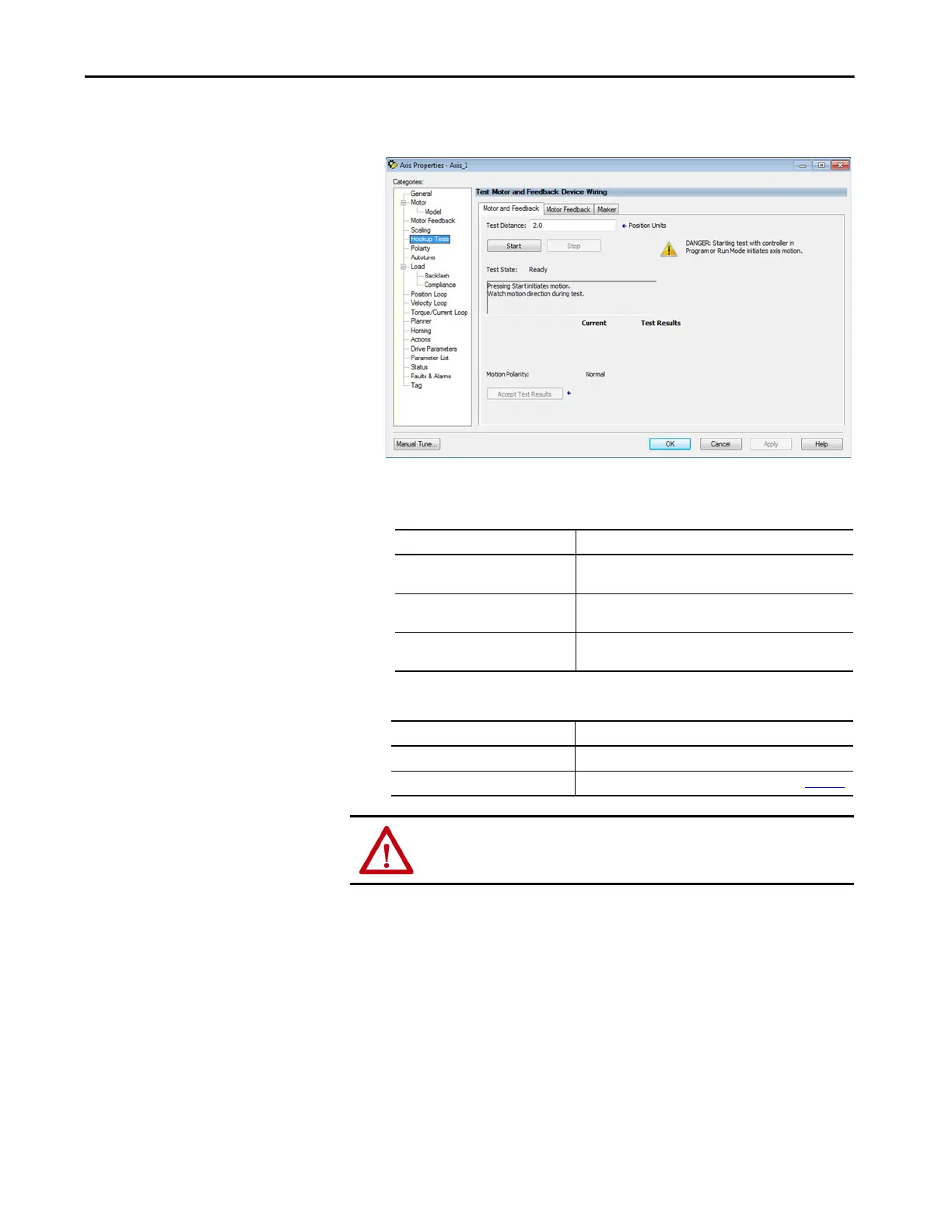
3. Click Hookup Tests category.
4. Type 2.0 as the number of revolutions for the test or another number
more appropriate for your application.
5.
6. Click the desired tab (Marker/Motor Feedback/Motor and Feedback).
In this example, the Motor and Feedback test is chosen.
7. Click Start.
This Test Performs this Test
Marker
Verifies marker detection capability as you rotate the motor
shaft.
Motor Feedback
Verifies that feedback connections are wired correctly as you
rotate the motor shaft.
Motor and Feedback
Verifies that motor power and feedback connections are wired
correctly as you command the motor to rotate.
If drive ENABLE is Then
Hard wired Apply 24V DC
Not used Disable enableInputChecking by using procedure on page 100
ATTENTION: To avoid personal injury or damage to equipment, apply
only24V ENABLE signal to the axis you are testing.

 Loading...


