Publication 1763-RM001C-EN-P - October 2009
Using the High-Speed Counter and Programmable Limit Switch 115
overflow value (counts are not lost in this transition). The user can specify
any value for the underflow position, provided it is less than the overflow
value and falls between -2,147,483,648 and 2,147,483,647.
To load data into the underflow variable, the control program must toggle
(low to high) the Set Parameters (HSC:0.0/SP) control bit. When the SP bit
is toggled high, the data currently stored in the HSC function file is
transferred/loaded into the HSC sub-system.
Output Mask Bits (OMB)
The OMB (Output Mask Bits) define which outputs on the controller can
be directly controlled by the high-speed counter. The HSC sub-system has
the ability to directly (without control program interaction) turn outputs
ON or OFF based on the HSC accumulator reaching the High or Low
presets. The bit pattern stored in the OMB variable defines which outputs
are controlled by the HSC and which outputs are not controlled by the
HSC.
The bit pattern of the OMB variable directly corresponds to the output bits
on the controller. Bits that are set (1) are enabled and can be turned on or
off by the HSC sub-system. Bits that are clear (0) cannot be turned on or
off by the HSC sub-system. The mask bit pattern can be configured only
during initial setup.
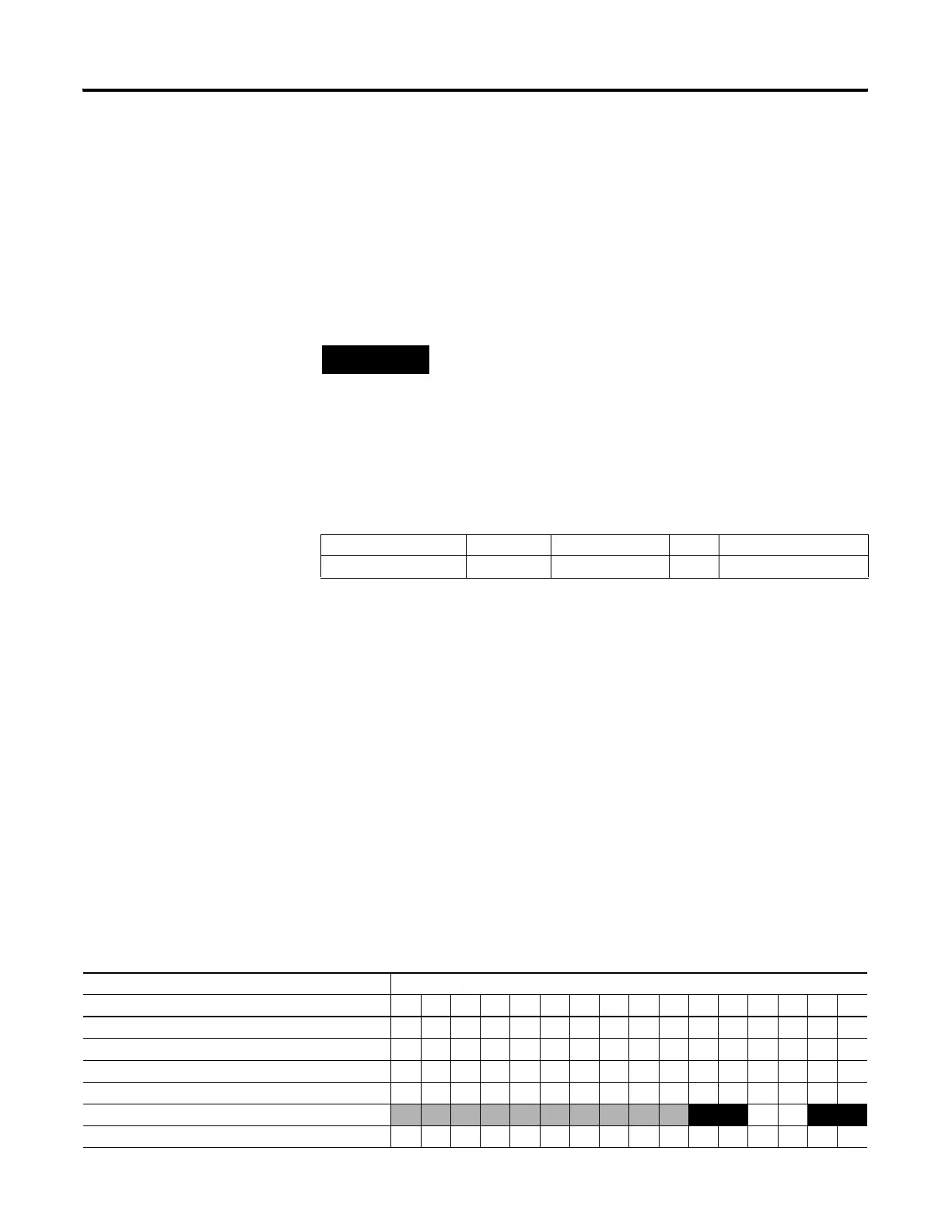
The table below illustrates this relationship:
TIP
Data loaded into the overflow variable must be greater
than the data resident in the high preset (HSC:0.HIP) or
an HSC error is generated.
Description Address Data Format Type User Program Access
OMB - Output Mask Bits HSC:0.OMB word (16-bit binary) control read only
Affect of HSC Output Mask on Base Unit Outputs
Output Address 16-Bit Signed Integer Data Word
1514131211109876543210
HSC:0.HPO (high preset output) 011001
HSC:0.OMB (output mask) 110011
O0:0.0
0 1 0 1
efesotomasyon.com - Allen Bradley,Rockwell,plc,servo,drive

 Loading...


