Publication 1763-RM001C-EN-P - October 2009
18 I/O Configuration
Analog I/O Configuration
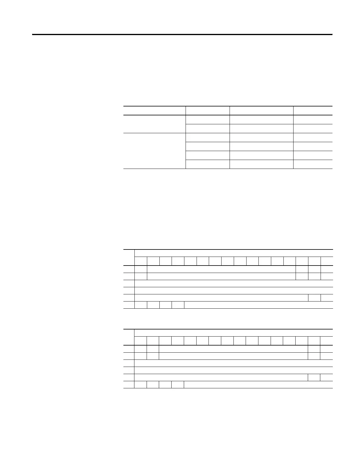
The following table shows the data ranges for 0 to 10V dc and 4 to 20 mA.
1762-IF2OF2 Input Data File
For each input module, slot x, words 0 and 1 contain the analog values of
the inputs. The module can be configured to use either raw/proportional
data or scaled-for-PID data. The input data file for each configuration is
shown below.
The bits are defined as follows:
• Sx = General status bits for channels 0 and 1. This bit is set when an
error (over- or under-range) exists for that channel, or there is a
general module hardware error.
Valid Input/Output Data Word Formats/Ranges
Normal Operating Range Full Scale Range Raw/Proportional Data Scaled-for-PID
0 to 10V dc 10.5V dc 32,760 16,380
0.0V dc 0 0
4 to 20 mA 21.0 mA 32,760 16,380
20.0 mA 31,200 15,600
4.0 mA 6240 3120
0.0 mA 0 0
Raw/Proportional Format
Word
Bit Position
15 14 13 12 11 10 9 8 7 6 5 4 3 2 1 0
0 0 Channel 0 Data 0 to 32,768 0 0 0
1 0 Channel 1 Data 0 to 32,768 0 0 0
2 reserved
3 reserved
4 reserved S1 S0
5 U0O0U1O1reserved
Scaled-for-PID Format
Word
Bit Position
15 14 13 12 11 10 9 8 7 6 5 4 3 2 1 0
0 0 0 Channel 0 Data 0 to 16,383 0 0
1 0 0 Channel 1 Data 0 to 16,383 0 0
2 reserved
3 reserved
4 reserved S1 S0
5 U0O0U1O1reserved
efesotomasyon.com - Allen Bradley,Rockwell,plc,servo,drive

 Loading...


