Publication 1763-RM001C-EN-P - October 2009
I/O Configuration 23
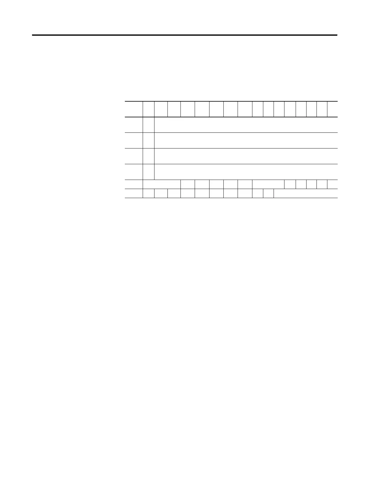
1762-IT4 Thermocouple Module Input Data File
For each module, slot x, words 0 through 3 contain the analog values of
the inputs. The input data file is shown below.
The bits are defined as follows:
• Sx = General status bits for channels 0 through 3 (S0 through S3)
and the CJC sensor (S4). This bit is set (1) when an error
(over-range, under-range, open-circuit, or input data not valid)
exists for that channel. An input data not valid condition is
determined by the user program. Refer to MicroLogix 1200 I/O
Thermocouple/mV Input Module User Manual, publication
1762-UM002 for additional details.
• OCx = Open-circuit indication for channels 0 through 3 (OC0
through OC3) and the CJC sensor (OC4).
• Ox = Over-range flag bits for channels 0 through 3 (O0 through O3)
and the CJC sensor (O4). These bits can be used in the control
program for error detection.
• Ux = Under-range flag bits for channels 0 through 3 (U0 through
U3) and the CJC sensor (U4). These bits can be used in the control
program for error detection.
Word/
Bit
15141312 11 10 9 8 76543210
0
SGN
Analog Input Data Channel 0
1
SGN
Analog Input Data Channel 1
2
SGN
Analog Input Data Channel 2
3
SGN
Analog Input Data Channel 3
4 Reserved OC4 OC3 OC2 OC1 OC0 Reserved S4 S3 S2 S1 S0
5 U0O0U1O1 U2 O2 U3 O3 U4O4Reserved
efesotomasyon.com - Allen Bradley,Rockwell,plc,servo,drive

 Loading...


