EasyManuals Logo

Allen-Bradley MicroLogix 1100 Instruction Set Reference Manual

Allen-Bradley MicroLogix 1100
616 pages
To Next Page IconTo Next Page
To Previous Page IconTo Previous Page
Page #350 background imageLoading...
Page #350 background image
Publication 1763-RM001B-EN-P - April 2007
350 Communications Instructions
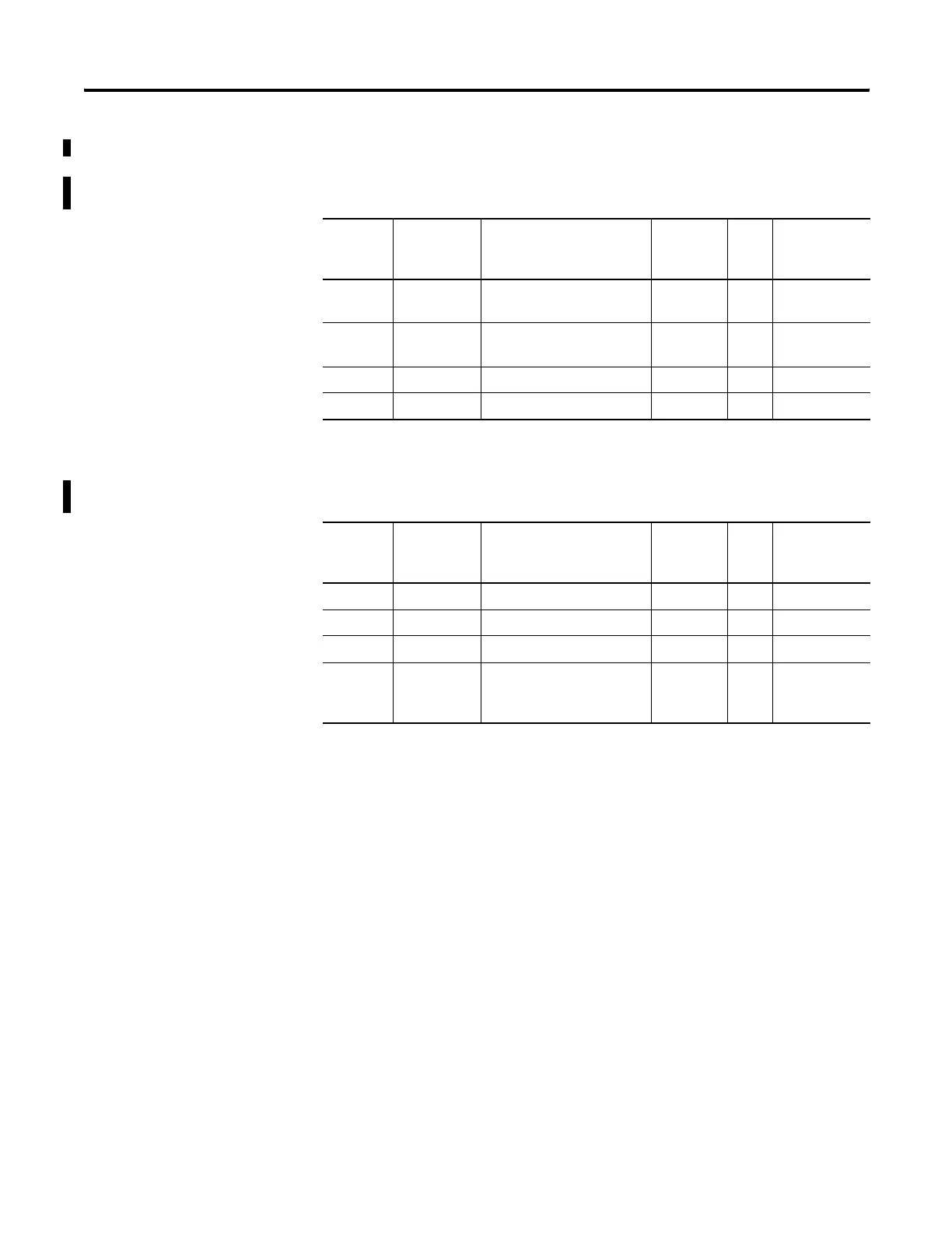
The Control Bits, Sub-Element 16, of the MSG File Element are defined
below:
Message File Target Location Information
Target Device = Modbus Device
Sub-
Element
Name Description Paramete
r
Size User
Program
Access
12 starting bit address for coils
and inputs
Y Word read only
13 MG11:0.TFN Modbus Target Data
Address - 1
Y Word read/write
14 Reserved Y Word read/write
15 Reserved Y Word read only
Message File Target Location Information
Target Device = CIP Generic (The MicroLogix 1100 OS Series B only)
Sub-
Element
Name Description Paramete
r
Size User
Program
Access
12 Target Class Y Word read only
13 Target Instance Y Word read/write
14 CIP Send Data Count Y Word read/write
15 Internal Physical Address of
CIP Send Data Table
Address operand
Y Word read only
efesotomasyon.com - Allen Bradley,Rockwell,plc,servo,drive

Table of Contents

Other manuals for Allen-Bradley MicroLogix 1100

Questions and Answers:

Question and Answer IconNeed help?

Do you have a question about the Allen-Bradley MicroLogix 1100 and is the answer not in the manual?

Allen-Bradley MicroLogix 1100 Specifications

General IconGeneral
Processor32-bit
Programming SoftwareRSLogix 500
MountingDIN rail or panel mount
Power Supply24V DC
TypeCompact PLC
Digital Inputs12
Digital Outputs8
Analog Inputs4 (depending on model)
Analog OutputsOptional with expansion module
Programming LanguageLadder Logic
Operating Temperature0 to 55 °C (32 to 131 °F)
SeriesMicroLogix

Related product manuals