EasyManuals Logo

Allen-Bradley MicroLogix 1100 Instruction Set Reference Manual

Allen-Bradley MicroLogix 1100
616 pages
To Next Page IconTo Next Page
To Previous Page IconTo Previous Page
Page #353 background imageLoading...
Page #353 background image
Publication 1763-RM001B-EN-P - April 2007
Communications Instructions 353
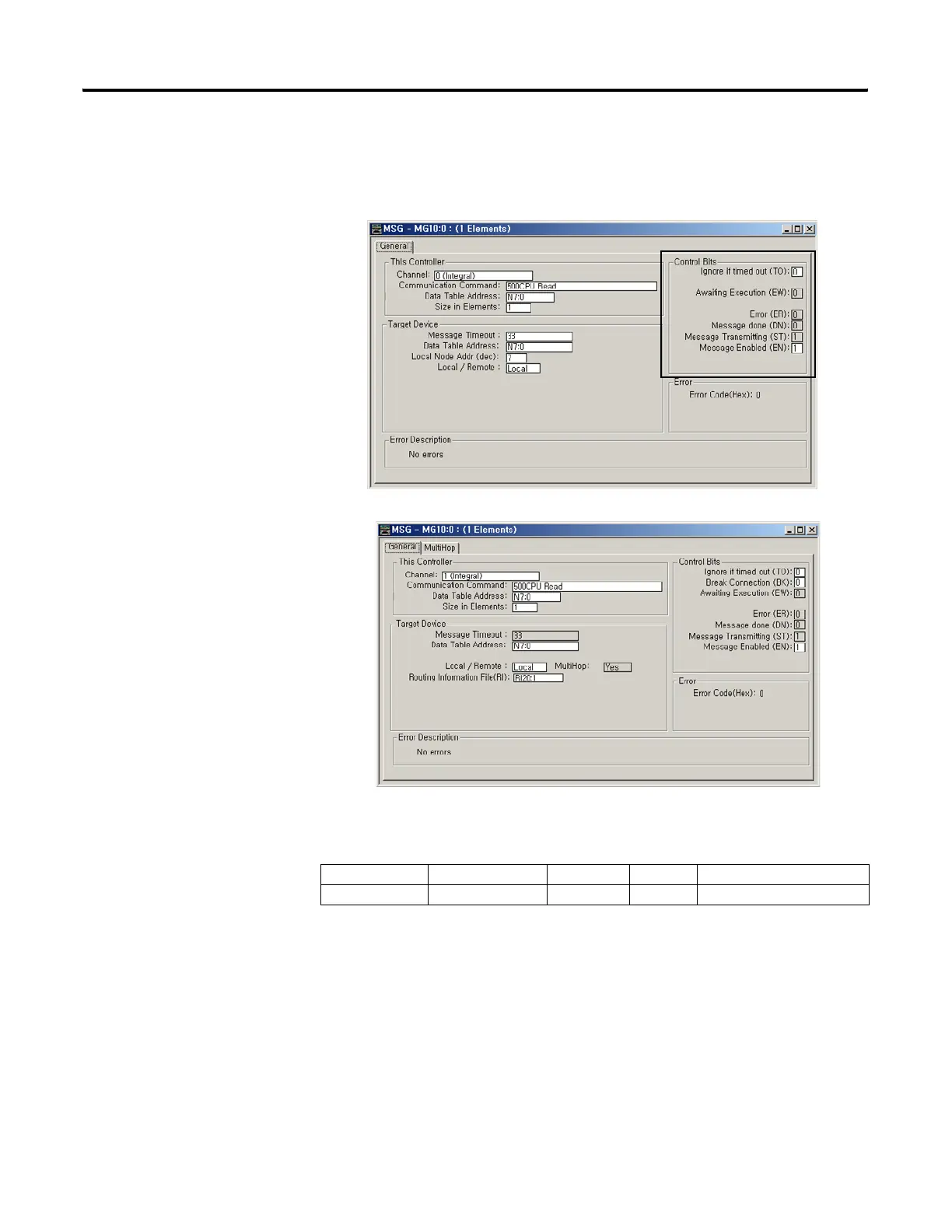
“Control Bits” Parameters
Channel 0 Setup Screen
Channel 1 Setup Screen
Ignore if Timed Out (TO)
The Timed Out Bit (TO) can be set in your application to remove an
active message instruction from processor control. You can create your
own timeout routine by monitoring the EW and ST bits to start a timer.
When the timer times out, you can set the TO bit, which removes the
message from the system. The controller resets the TO bit the next time
the associated MSG rung goes from false to true.
Address Data Format Range Type User Program Access
MG11:0/TO Binary On or Off Control Read / Write
efesotomasyon.com - Allen Bradley,Rockwell,plc,servo,drive

Table of Contents

Other manuals for Allen-Bradley MicroLogix 1100

Questions and Answers:

Question and Answer IconNeed help?

Do you have a question about the Allen-Bradley MicroLogix 1100 and is the answer not in the manual?

Allen-Bradley MicroLogix 1100 Specifications

General IconGeneral
Processor32-bit
Programming SoftwareRSLogix 500
MountingDIN rail or panel mount
Power Supply24V DC
TypeCompact PLC
Digital Inputs12
Digital Outputs8
Analog Inputs4 (depending on model)
Analog OutputsOptional with expansion module
Programming LanguageLadder Logic
Operating Temperature0 to 55 °C (32 to 131 °F)
SeriesMicroLogix

Related product manuals