Publication 1763-RM001B-EN-P - April 2007
Communications Instructions 355
Error (ER)
The Error Bit (ER) is set when message transmission has failed. An error
code is written to the MSG File. The ER bit and the error code are cleared
the next time the associated rung goes from false to true.
Done (DN)
The Done Bit (DN) is set when the message is transmitted successfully.
The DN bit is cleared the next time the associated rung goes from false to
true.
Start (ST)
The Start Bit (ST) is set when the processor receives acknowledgment
(ACK) from the target device. The ST bit is cleared when the DN, ER, or
TO bit is set.
The DF1 Radio Modem and Modbus RTU Master protocols do not have
acknowledgements. When the channel that the MSG instruction is being
initiated on is configured for either of these two drivers, the Start Bit (ST)
is set when the message has been successfully transmitted.
Break Connection (BK))
When the Break bit is used by the true, the Ethernet/IP connection will be
closed after the MSG instruction is processed. If set to 0 value, the
Ethernet/IP connection will remain even if the MSG instruction sent
successfully.(MicroLogix 1100 OS Series B FRN 4 or later only)
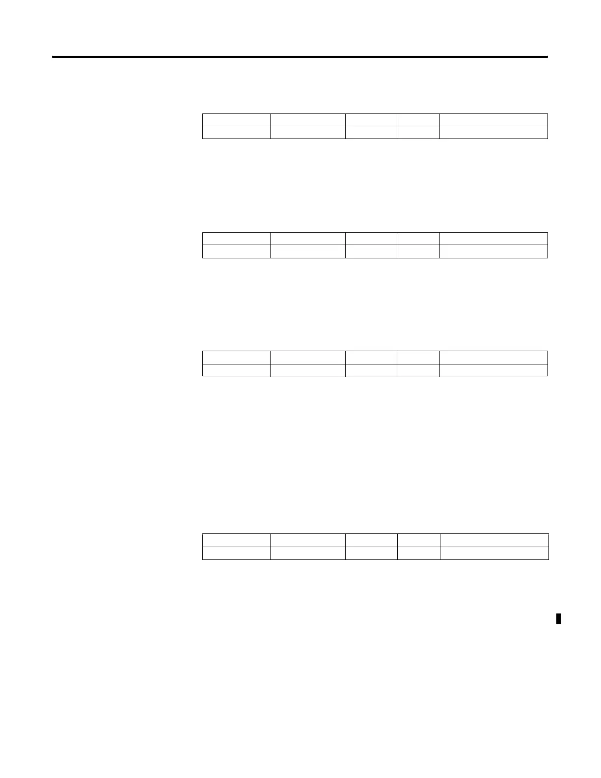
Address Data Format Range Type User Program Access
MG11:0/ER Binary On or Off Status Read Only
Address Data Format Range Type User Program Access
MG11:0/DN Binary On or Off Status Read Only
Address Data Format Range Type User Program Access
MG11:0/ST Binary On or Off Status Read Only
Address Data Format Range Type User Program Access
MG11:0/BK Binary On or Off Control Read / Write
efesotomasyon.com - Allen Bradley,Rockwell,plc,servo,drive

 Loading...


