Publication 1763-RM001B-EN-P - April 2007
Communications Instructions 383
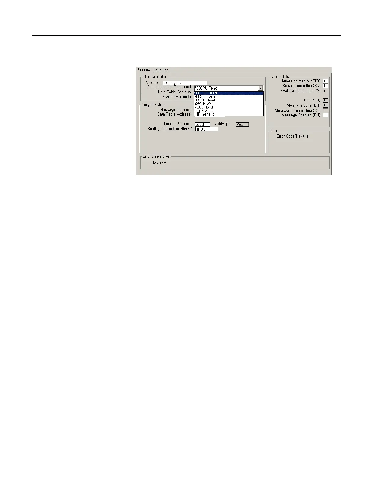
“Target Device” Parameters
Message Timeout
Message Timeout for any MicroLogix 1100 channel 1 MSG cannot be
modified in the Ethernet Message Setup dialog box. It is assigned by the
processor and is determined by adding the Channel 1 MSG Connection
Timeout to the MSG Reply Timeout, then adding 15 seconds. This value
can be modified by changing one or both of the timeout values in the
channel configuration screen for channel 1. The modified message
timeout applies to all Ethernet MSG instructions.
Routing Information File
The Routing Information (RI) File stores the path for reaching the
destination node. Each RI File Element consists of Sub-Elements 0 through
19 as shown in the following table.
To reach another MicroLogix 1100, an SLC 5/05, a PLC-5E or a controller
connected to Ethernet via a 1761-NET-ENI, simply enter in the destination
IP address.
efesotomasyon.com - Allen Bradley,Rockwell,plc,servo,drive

 Loading...


