EasyManuals Logo

Allen-Bradley MicroLogix 1100 Instruction Set Reference Manual

Allen-Bradley MicroLogix 1100
616 pages
To Next Page IconTo Next Page
To Previous Page IconTo Previous Page
Page #400 background imageLoading...
Page #400 background image
Publication 1763-RM001B-EN-P - April 2007
400 Communications Instructions
Enter in the destination node address (DH+ octal address of target
processor) under the To Address.
Note: Make sure that the Target Device Data Table Address exists in the
target device.
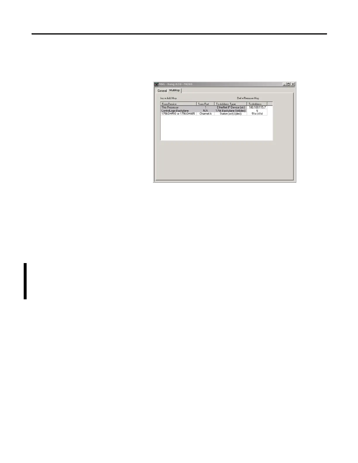
Network Message Example 2:
MicroLogix 1100 Ethernet to SLC 5/03 DH485 via ENET, DHRIO and
1785-KA5 bridge device (OS Series B FRN 4 or later)
The following illustrates the MicroLogix 1100 OS Series B(CH1 Ethernet)
sending a remote message to a SLC5/03 processor (DH+ Node 51). The
remote message will passthru an ENET module, a ControlLogix chassis
(Gateway), a DHRIO module and a 1785-KA5 bridge device. In order for
the message to pass through the network, a multiHop MSG must be setup
efesotomasyon.com - Allen Bradley,Rockwell,plc,servo,drive

Table of Contents

Other manuals for Allen-Bradley MicroLogix 1100

Questions and Answers:

Question and Answer IconNeed help?

Do you have a question about the Allen-Bradley MicroLogix 1100 and is the answer not in the manual?

Allen-Bradley MicroLogix 1100 Specifications

General IconGeneral
Processor32-bit
Programming SoftwareRSLogix 500
MountingDIN rail or panel mount
Power Supply24V DC
TypeCompact PLC
Digital Inputs12
Digital Outputs8
Analog Inputs4 (depending on model)
Analog OutputsOptional with expansion module
Programming LanguageLadder Logic
Operating Temperature0 to 55 °C (32 to 131 °F)
SeriesMicroLogix

Related product manuals