EasyManuals Logo

Allen-Bradley MicroLogix 1100 Instruction Set Reference Manual

Allen-Bradley MicroLogix 1100
616 pages
To Next Page IconTo Next Page
To Previous Page IconTo Previous Page
Page #402 background imageLoading...
Page #402 background image
Publication 1763-RM001B-EN-P - April 2007
402 Communications Instructions
Go to the routing table configuration tab. Right-click on the DHRIO
channel being used and select Add Module. Select the DH+ Bridge. Enter
the DH+ node number of the KA5 (37 in this example), and the Link ID of
the DH485 (13 in this example). Click Apply.
You can now browse through the KA5 module from RSWho.
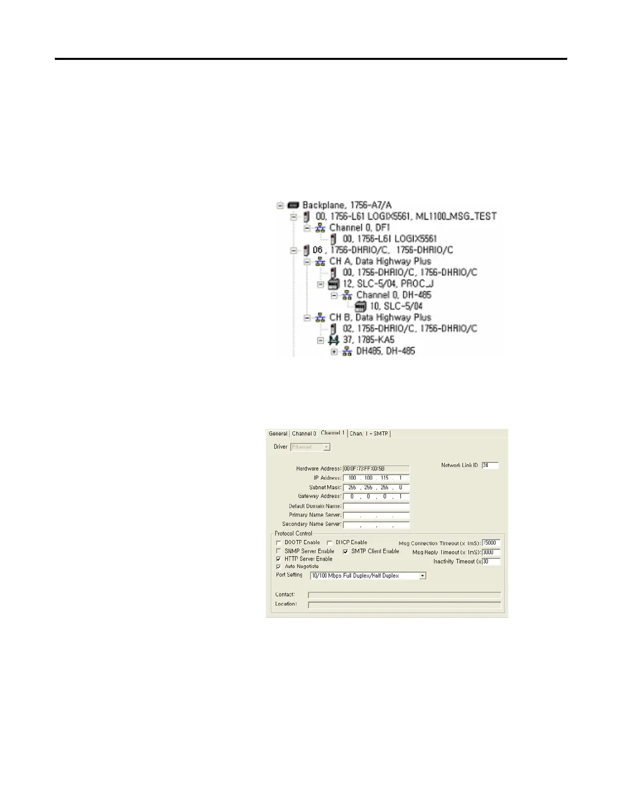
ML1100 Channel1 Configuration
The following is the message setup screen for the MicroLogix 1100
controller.
efesotomasyon.com - Allen Bradley,Rockwell,plc,servo,drive

Table of Contents

Other manuals for Allen-Bradley MicroLogix 1100

Questions and Answers:

Question and Answer IconNeed help?

Do you have a question about the Allen-Bradley MicroLogix 1100 and is the answer not in the manual?

Allen-Bradley MicroLogix 1100 Specifications

General IconGeneral
Processor32-bit
Programming SoftwareRSLogix 500
MountingDIN rail or panel mount
Power Supply24V DC
TypeCompact PLC
Digital Inputs12
Digital Outputs8
Analog Inputs4 (depending on model)
Analog OutputsOptional with expansion module
Programming LanguageLadder Logic
Operating Temperature0 to 55 °C (32 to 131 °F)
SeriesMicroLogix

Related product manuals