Publication 1763-RM001C-EN-P - October 2009
432 Recipe and Data Logging
When B3:0/2 is energized and B3:0/0 and B3:0/1 are de-energized, Recipe
File 0:Recipe number 2 is executed loading the following values to create
White paint.
• N7:0 = 333
• N7:1 = 333
• N7:2 = 333
• T4:0.PRE = 1000
Monitor the N7 data file. Notice the values change after each bit is
toggled.
This example describes loading values from a RCP file to data table
addresses. However, note that by changing the RCP file operation from
Load to Store, values can be loaded by ladder logic into the recipe
database for each Recipe number.
Calculation of Consumed Memory
The consumed memory in this example can be calculated by the
following equation.
Consumed memory size for Recipe File 0
= Data Field per a recipe * Number of Recipes
= 10 * 3 (bytes)
= 30 bytes
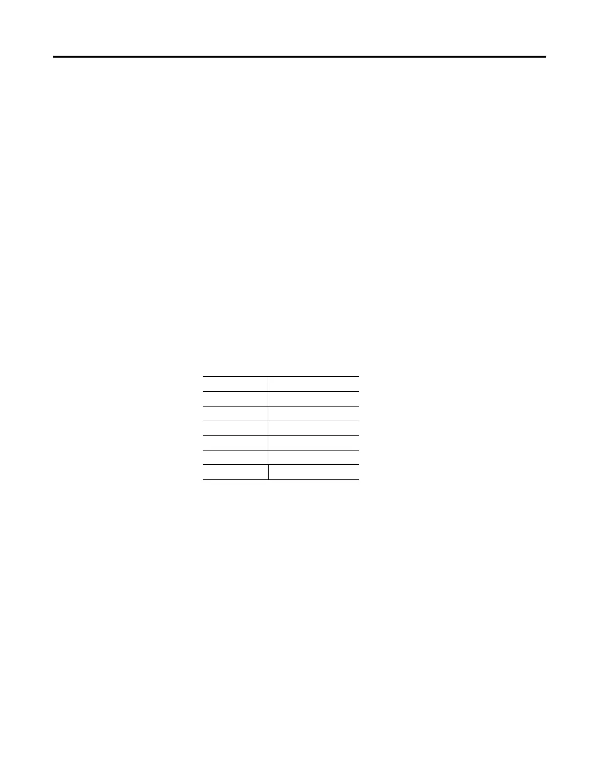
Data Field Memory Consumption
N7:0 2-byte
N7:1 2-byte
N7:2 2-byte
T4:0.PRE 2-byte
Integrity Check 2-byte
Total 10-byte
efesotomasyon.com - Allen Bradley,Rockwell,plc,servo,drive

 Loading...


