Publication 1763-RM001C-EN-P - October 2009
System Status File 471
See also:LE - Load on Error on page 56.
Load Memory Module Always
For this option to work, you must set (1) this bit in the control program
before downloading the program to a memory module. When this bit is
set in the memory module and power is applied, the controller
downloads the memory module program.
The mode of the controller after the transfer takes place is determined by
the controller mode switch and the Power-Up Mode Behavior Selection
bit (S:1/12).
See also:LA - Load Always on page 56.
Power-Up Mode Behavior
If Power-Up Mode Behavior is clear (0 = Last State), the mode at
power-up is dependent upon the:
• position of the mode switch
• state of the Major Error Halted flag (S:1/13)
• mode at the previous power down
If Power Up Mode Behavior is set (1 = Run), the mode at power-up is
dependent upon the:
• position of the mode switch
• state of the Major Error Halted flag (S:1/13)
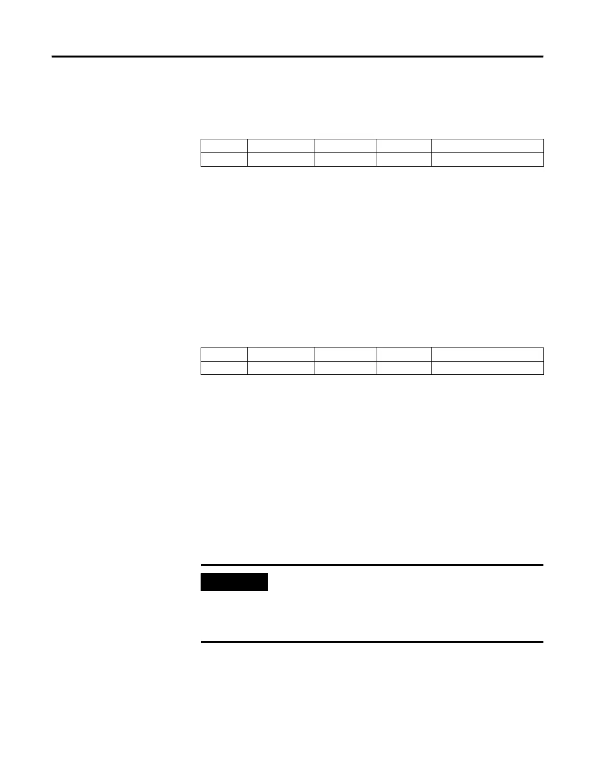
Address Data Format Range Type User Program Access
S:1/11 binary 0 or 1 control read only
Address Data Format Range Type User Program Access
S:1/12 binary 0 or 1 control read only
IMPORTANT
If you want the controller to power-up and enter the Run
mode, regardless of any previous fault conditions, you
must also set the Fault Override bit (S:1/8) so that the
Major Error Halted flag is cleared before determining the
power up mode.
efesotomasyon.com - Allen Bradley,Rockwell,plc,servo,drive

 Loading...


