Publication 1763-RM001C-EN-P - October 2009
472 System Status File
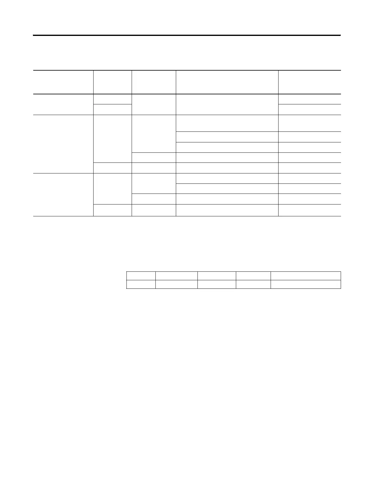
The following table shows the Power-Up Mode under various conditions
See also:MB - Mode Behavior on page 56.
Major Error Halted
The controller sets (1) this bit when a major error is encountered. The
controller enters a fault condition and word S:6 contains the Fault Code
that can be used to diagnose the condition. Any time bit S:1/13 is set, the
controller:
• turns all outputs off and flashes the FAULT LED,
• or, enters the User Fault Routine allowing the control program to
attempt recovery from the fault condition. If the User Fault Routine
is able to clear S:1/13 and the fault condition, the controller
continues to execute the control program. If the fault cannot be
cleared, the outputs are cleared and the controller exits its executing
mode and the FAULT LED flashes.
MicroLogix 1100 -
Mode Switch Position
at Power-Up
Major Error
Halted
Power-Up
Mode Behavior
Mode at Last Power-Down Power-Up Mode
Program False Don’t Care Don’t Care Program
True Program w/Fault
Remote False Last State REM Download, Download, REM Program,
Program or Any Test mode
REM Program
REM Suspend or Suspend REM Suspend
REM Run or Run REM Run
Run Don’t Care REM Run
True Don’t Care Don’t Care REM Program w/Fault
Run False Last State REM Suspend or Suspend Suspend
Any Mode except REM Suspend or Suspend Run
Run Don’t Care Run
True Don’t Care Don’t Care
Run w/Fault
(1)
(1) Run w/Fault is a fault condition, just as if the controller were in the Program /w Fault mode (outputs are reset and the controller program is not being executed). However,
the controller enters Run mode as soon as the Major Error Halted flag is cleared.
Address Data Format Range Type User Program Access
S:1/13 binary 0 or 1 status read/write
efesotomasyon.com - Allen Bradley,Rockwell,plc,servo,drive

 Loading...


