Publication 1763-RM001C-EN-P - October 2009
System Status File 481
Active Nodes (Nodes 16 to 31)
This address is duplicated in the Communications Status File (CSx:0.28).
SeeActive Node Table Block on page 69 for more information.
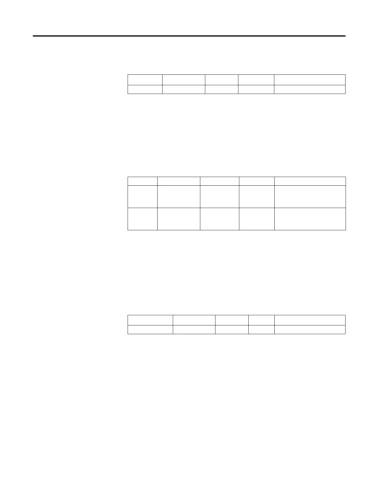
Math Register
These two words are used in conjunction with the MUL, DIV, FRD, and
TOD math instructions. The math register value is assessed upon
execution of the instruction and remains valid until the next MUL, DIV,
FRD, or TOD instruction is executed in the user program.
Node Address
This address is duplicated in the Communications Status File (CSx:0.5/0
through CSx:0.5/7). SeeGeneral Channel Status Block on page 58 for more
information.
Address
(1)
(1) This bit can only be accessed via ladder logic. It cannot be accessed via communications (such as a Message
instruction from another device).
Data Format Range Type User Program Access
S:10 word 0 to FFFF status read only
Address Data Format Range Type User Program Access
S:13
(low byte)
word -32,768 to
+32,767
status read/write
S:14
(high byte)
word -32,768 to
+32,767
status read/write
Address
(1)
(1) This byte can only be accessed via ladder logic. It cannot be accessed via communications (such as a Message
instruction from another device).
Data Format Range Type User Program Access
S:15 (low byte) byte 0 to 255 status read only
efesotomasyon.com - Allen Bradley,Rockwell,plc,servo,drive

 Loading...


